Orthodontic apparatus and method

Inactive Publication Date: 2008-10-09
GRIFFITH RICHARD J +1
View PDF33 Cites 29 Cited by
  • Summary
  • Abstract
  • Description
  • Claims
  • Application Information

AI Technical Summary

Benefits of technology

[0012]The present invention is directed toward increasing the efficiency of force applications in orthodontics and improving the co

Problems solved by technology

Although friction may have a positive effect in some instances it is usually associated with detrimental effects.
Thus, the tendency is for sliding mechanics to tax anchorage units (cause undesirable movement of a tooth or teeth that are used in the process of applying forces to a tooth or teeth for which movement is desired).
At least two problems occur with this treatment structure and methodology.
First, the lo

Method used


Image

  • Orthodontic apparatus and method
  • Orthodontic apparatus and method
  • Orthodontic apparatus and method

Examples


Example

[0091]The drawings will be better understood when reference is made to the Description of the Invention and Claims which follow hereinbelow.

DESCRIPTION OF THE INVENTION

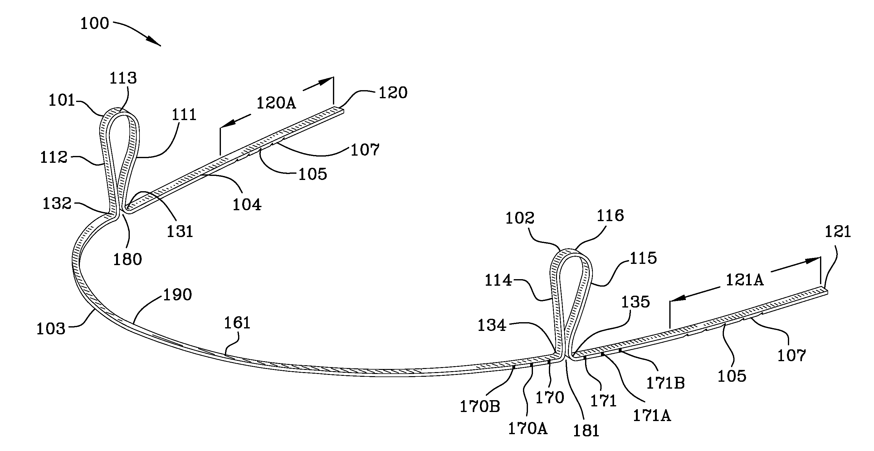
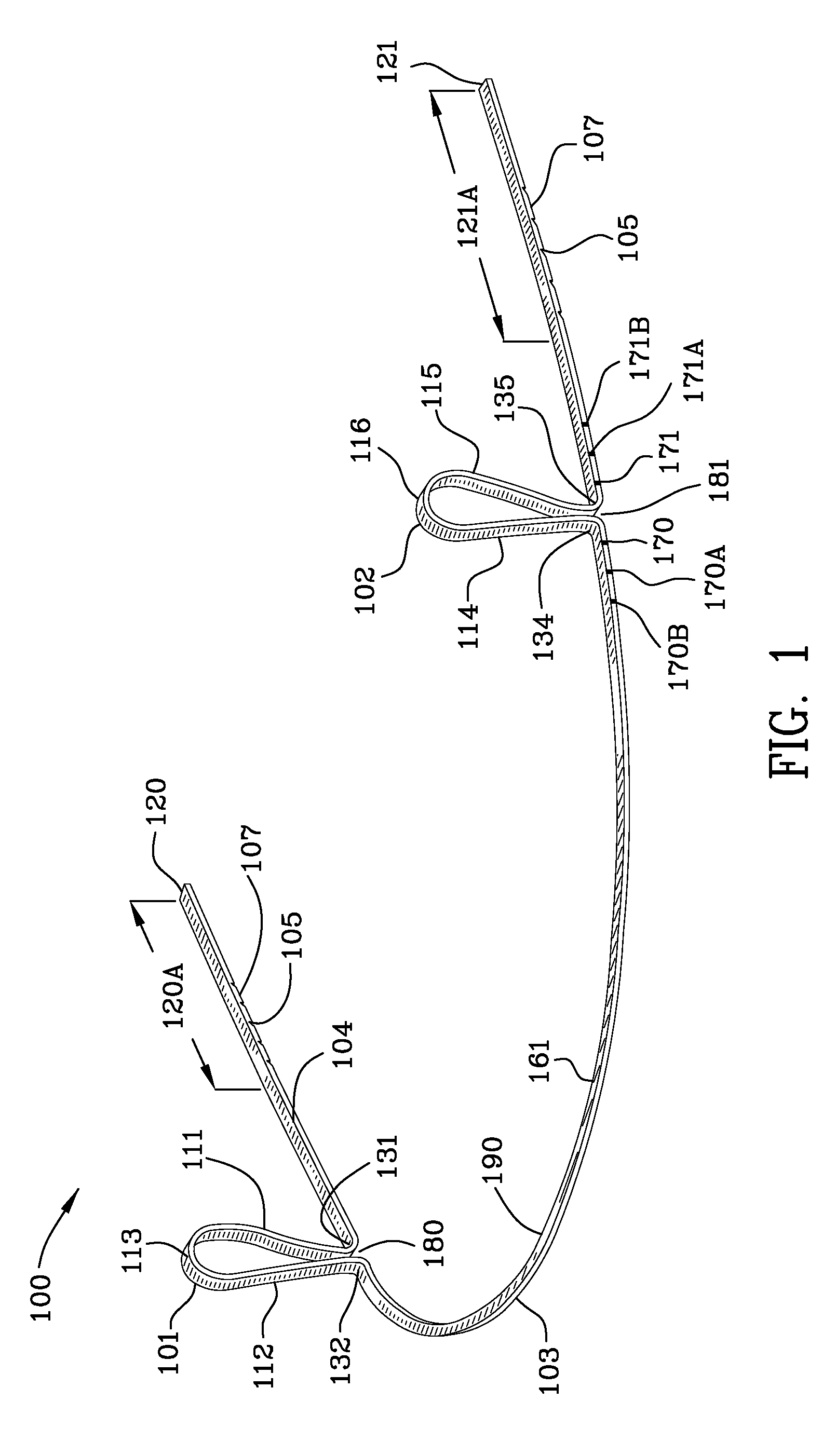
[0092]In referring to the drawings hereinbelow the application of a load is described herein without always indicating that a load is applied or showing structure necessary to create the load.

[0093]FIG. 1 is a perspective view 100 of an example of an extendable archwire (103, 104, 161, 190) with unloaded open-loop springs 101, 102, calibration marks (indicia) (170, 170A, 170B, 171, 171A, 171B) located in proximity to the open-loop springs, and adjustment portions 120A, 121A of the archwire near the ends 120, 121 of the archwire having notches 105 therein. The first open-loop spring 101 has legs 111, 112 and an intermediate portion 113. Bends 131, 132 in the archwire form the desired loop-spring shape with gap 180 between the legs of the spring.

[0094]Second open-loop spring 102 has legs 114, 115 and an intermediate por...


PUM


Abstract

An orthodontic device includes a bracket having a body and the body includes external surfaces. An archwire passageway is formed in the body. An aperture extends from one of the external surfaces of the body to the passageway. A pawl is attached to the body and includes stop and cam surfaces which extend into the aperture. An extendable archwire includes an adjustment portion having a locking surface and a loop-spring therein and the adjustment portion is inserted into and through the passageway. The pawl and the locking surface form a ratchet. The cam surface of the pawl interengages the extendable archwire as the extendable archwire is extended through the bracket under the application of force to the extendable archwire. The stop surface of the pawl interengages the locking surface of the adjustment portion of the extendable archwire preventing retraction of the extendable archwire upon discontinuation of the application of force.

Description

FIELD OF INVENTION[0001]The present invention relates to the brackets and extendable archwires used in the dental specialty of orthodontics.BACKGROUND OF INVENTION[0002]U.S. Pat. No. 7,033,171 to Wilkerson discloses, as set forth in the abstract thereof, the following: “[a] molar tube having a first face portion that is adapted to be adhered to a molar tooth, a second face portion, and a mesial-distal length dimension. There is a body portion disposed on the second face portion of the base portion, and the body portion comprises an upper portion and a lower portion. The body portion further comprises a lumen that is adapted to receive an archwire, wherein the lumen has an axis which substantially coincides with the mesial-distal length dimension of the base portion. The body portion further comprises a boss comprising a threaded bore that is adapted to receive a setscrew, wherein the threaded bore has an axis. The axis of the threaded bore intersects with the mesial-distal length di...

Claims


Application Information

Patent Timeline
IPC IPC(8): A61C7/14
CPCA61C7/12A61C7/14A61C7/20A61C7/22
Inventor GRIFFITH, RICHARD J.KOENIG, WILLIAM
Owner GRIFFITH RICHARD J
Why Eureka
Try Eureka