A method of manufacturing a shear web using a pre-formed web foot flange

Active Publication Date: 2017-01-26
LM WP PATENT HLDG
View PDF10 Cites 32 Cited by
  • Summary
  • Abstract
  • Description
  • Claims
  • Application Information

AI Technical Summary

Benefits of technology

[0013]It is an object of the invention to provide an alternative system and method for the manufacture of wind turbine blade comp

Problems solved by technology

However, such systems require the provision of dedicated moulding tables for the formation of such shear webs, which can often be continuous structures in excess of 30-40 metres length, taking up considerable space in a blade factory.
Also, the application, infusion and subsequent curing of the fib

Method used


Image

  • A method of manufacturing a shear web using a pre-formed web foot flange
  • A method of manufacturing a shear web using a pre-formed web foot flange
  • A method of manufacturing a shear web using a pre-formed web foot flange

Examples


first embodiment

[0076]FIG. 4 shows a pre-cured web foot flange according to the invention,

second embodiment

[0077]FIG. 5 shows a pre-cured web foot flange according to the invention,

[0078]FIG. 6 illustrates a first embodiment of a manufacturing method according to the invention for manufacturing a shear web, and

[0079]FIG. 7 illustrates a second embodiment of a manufacturing method according to the invention for manufacturing a shear web.

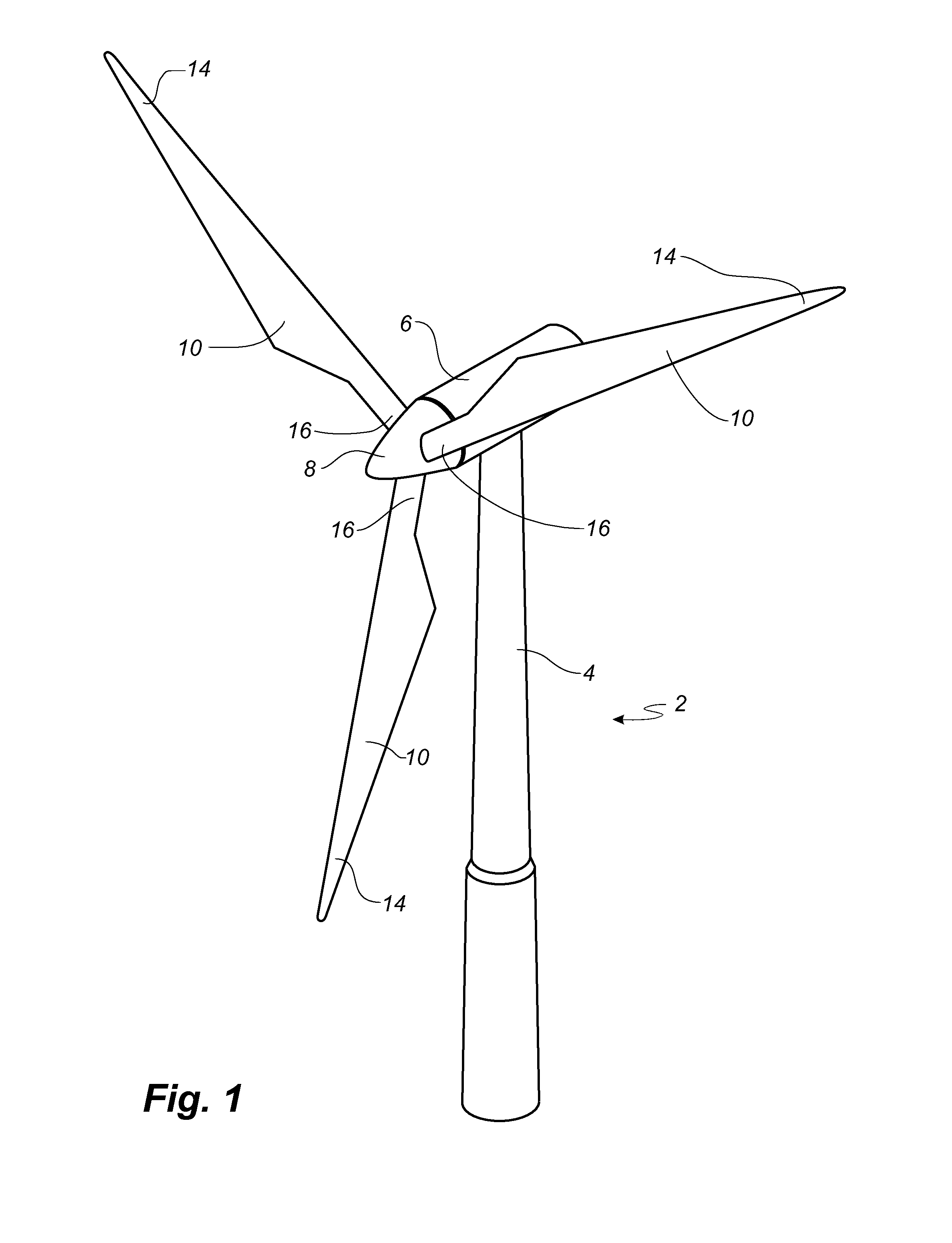
[0080]FIG. 1 illustrates a conventional modern upwind wind turbine according to the so-called “Danish concept” with a tower 4, a nacelle 6 and a rotor with a substantially horizontal rotor shaft. The rotor includes a hub 8 and three blades 10 extending radially from the hub 8, each having a blade root 16 nearest the hub and a blade tip 14 farthest from the hub 8. The rotor has a radius denoted R.

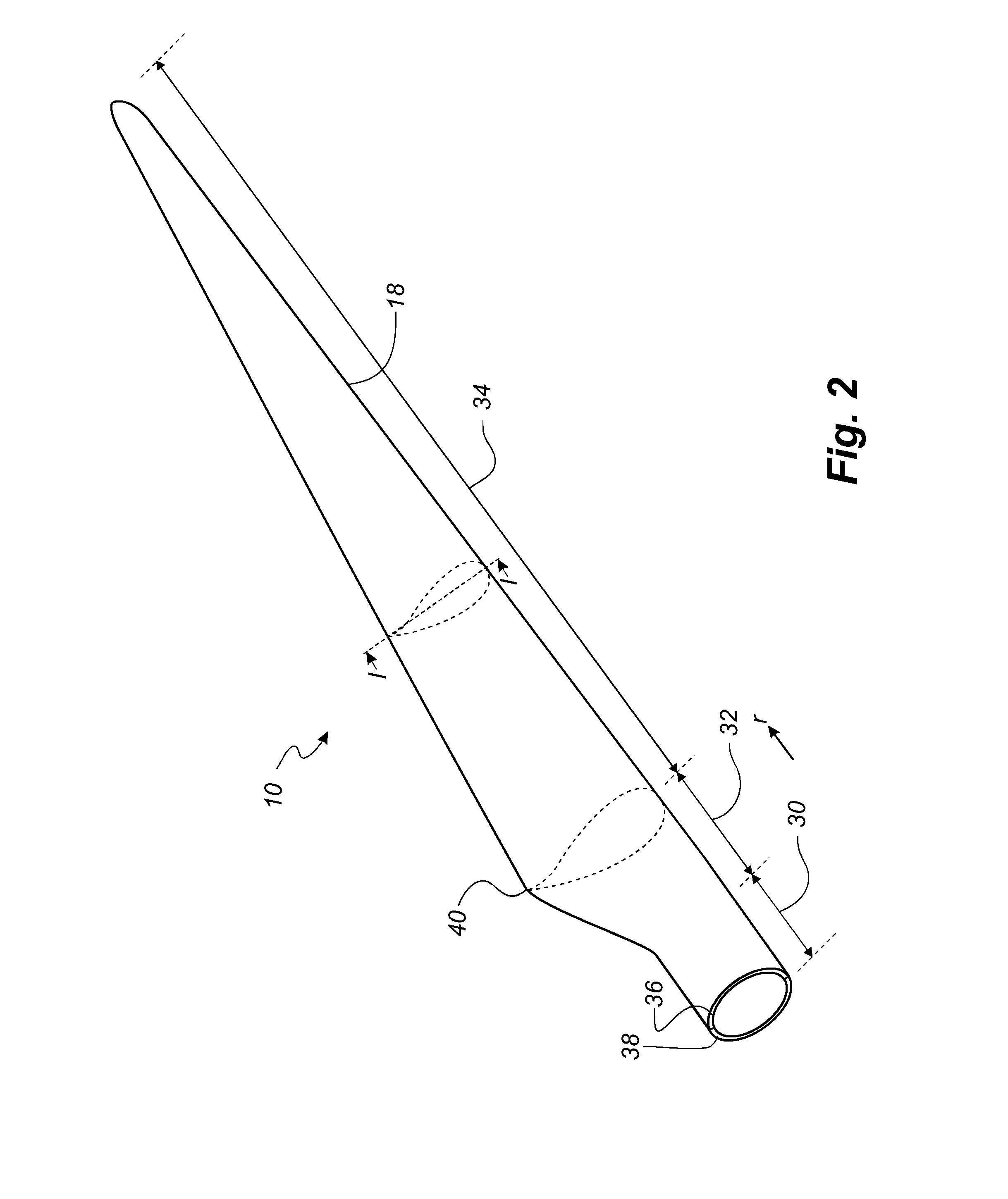
[0081]FIG. 2 shows a schematic view of a wind turbine blade 10. The wind turbine blade 10 has the shape of a conventional wind turbine blade and comprises a root region 30 closest to the hub, a profiled or an airfoil region 34 farthest away from the hub and a trans...


PUM

PropertyMeasurementUnit
Angleaaaaaaaaaa
Angleaaaaaaaaaa
Angleaaaaaaaaaa

Abstract

A method of manufacturing a wind turbine blade component in form of a shear web is described. The method comprising the steps of: a) providing a pre-manufactured shear web body having a first side and a second side as well as a first end and a second end; b) providing a first pre-formed web foot flange comprising a fibre-reinforcement material; c) arranging a first fibre layer from the first pre-formed web foot flange and to a part of the first side of the shear web body; d) arranging a second fibre layer from the first pre-formed web foot flange and to a part of the second side of the shear web body; e) supplying a resin to said first fibre layer and second fibre layer simultaneous with or subsequent to steps c) and d); and f) allowing the resin to cure so as to form the shear web.

Description

FIELD OF THE INVENTION[0001]The present invention relates to a method of manufacturing a wind turbine blade component in form of a shear web body, and a shear web body manufactured according to the method.BACKGROUND OF THE INVENTION[0002]Wind turbine blades are often manufactured according to one of two constructional designs, namely a design where a thin aerodynamic shell is glued or otherwise bonded onto a spar beam, or a design where spar caps, also called main laminates, are integrated into the aerodynamic shell.[0003]In the first design, the spar beam constitutes the load bearing structure of the blade. The spar beam as well as the aerodynamic shell or shell parts are manufactured separately. The aerodynamic shell is often manufactured as two shell parts, typically as a pressure side shell part and a suction side shell part. The two shell parts are glued or otherwise connected to the spar beam and are further glued to each other along a leading edge and trailing edge of the she...

Claims


Application Information

Patent Timeline
IPC IPC(8): B29C70/22B29C70/44
CPCB29C70/22B29L2031/085B29C70/443B29C70/342F03D1/0675Y02E10/72Y02P70/50B29D99/0005
Inventor HANSEN, TIM MOLLERRASMUSSEN, KIM ANSHOLMLUNDSGAARD-LARSEN, CHRISTIANPEDERSEN, STEVEN HAUGE
Owner LM WP PATENT HLDG
Why Eureka
Try Eureka