Cutting device

a cutting device and battery technology, applied in the direction of metal sawing accessories, portable power-driven tools, manufacturing tools, etc., can solve the problems of high cost, and achieve the effect of excellent grasping performance of the handle portion, and easy attachment and detachment of batteries

Inactive Publication Date: 2015-11-19
MAKITA CORP
View PDF12 Cites 31 Cited by
  • Summary
  • Abstract
  • Description
  • Claims
  • Application Information

AI Technical Summary

Benefits of technology

[0013]In accordance with an embodiment, the batteries may be capable of being attached to a region on a lower side of the handle portion. With this embodiment, the two batteries may not constitute an obstruction when the user grasps the handle, making it possible to ensure an excellent grasping performance of the handle portion.
[0014]In accordance with an embodiment, the attachment direction for the battery attachment portions may be perpendicular to a surface of the cutting blade. With this embodiment, it is possible to attach the batteries from a lateral side of the cutting blade, and, conversely, it is possible to detach the batteries by moving them toward the lateral side of the cutting blade, and therefore, when the cutting tool is placed on the floor in such a state that the side of the blade case opposite to the motor is oriented downward, it is possible to easily attach and detach the batteries to and from the battery attachment portions.
[0015]In accordance with an embodiment, the attachment direction for the battery attachmen

Problems solved by technology

However, conventionally, because an 18 V battery may not be applied to a high-output cutting tool using a 36 V battery as a dedicated power source, there may be nothing for it for the user but to separate

Method used


Image

  • Cutting device
  • Cutting device
  • Cutting device

Examples


first embodiment

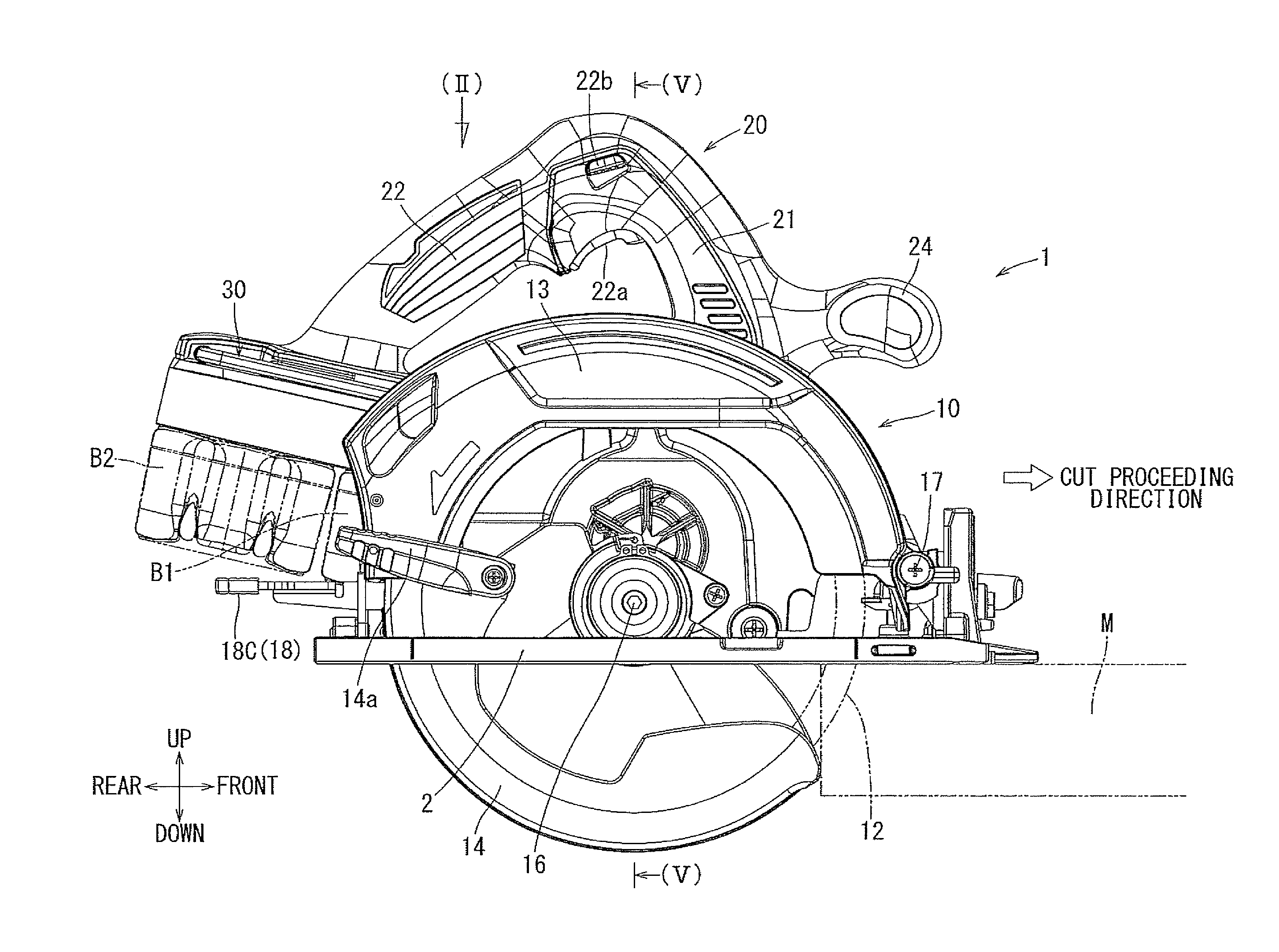
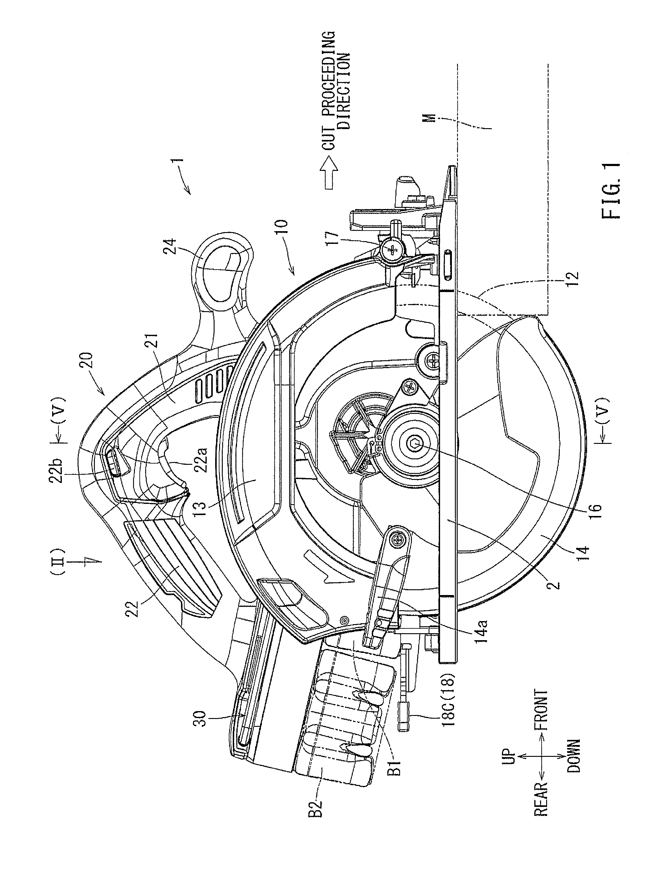
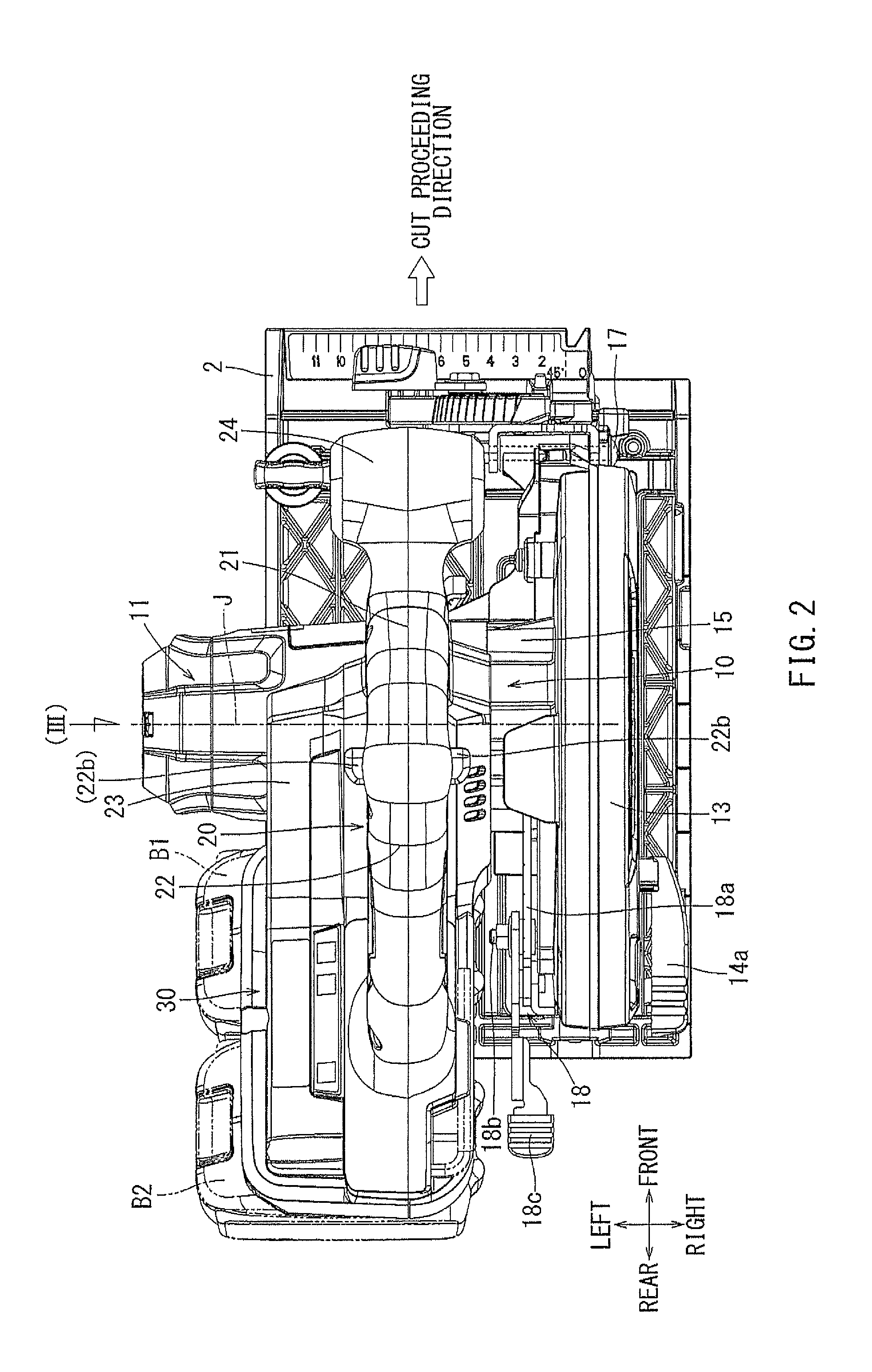
[0075]In the following, a first embodiment will be described with reference to FIGS. 1 through 6. FIG. 1 shows a rechargeable cutting tool 1 according to the embodiment. This cutting tool 1 may be a hand-held type cutting tool also called as a portable circular saw. The cutting tool 1 may include a base 2 formed substantially as a rectangular flat plate and adapted to contact with the upper surface of a workpiece M to be cut. The cutting tool 1 may further include a cutting tool main body 10 supported on the upper surface side of the base 2.

[0076]The cutting tool main body 10 may include an electric motor 11 configured to function as a drive source. The cutting tool main body 10 may further include a circular cutting blade 12 rotated by the electric motor 11. The range of the upper circumferential half of the cutting blade 12 may be covered with a blade case 13. The range of the lower circumferential half of the cutting blade 12 may be covered with a movable cover 14. The movable co...

second embodiment

[0103]The second embodiment will be described with reference to FIGS. 7 through 9. The second embodiment relates to a woodworking circular saw. The woodworking circular saw may be of a rated voltage of 36 V, and may use, as a power source, two 18 V batteries 110 connected in series. This second embodiment may be substantially the same as a conventionally well-known woodworking circular saw, with the exception that the two batteries 110 may be used and connected in series, so a detailed description of a traditional woodworking circular saw will be omitted. In FIGS. 7 and 9, a direction indicated by an outline arrow with a labeling of “cut proceeding direction” may be the direction in which the woodworking circular saw moves while being pushed when the woodworking circular saw is used for cutting, that is, it indicates the wood cutting direction. Further, in FIGS. 7 through 9, the directions indicated by the crossing arrows may indicate the directions as labeled therein, with referenc...

third embodiment

[0109]The third embodiment will be described with reference to FIGS. 10 through 12. The third embodiment may differ from the second embodiment in that the attachment positions of the two batteries 110 in the woodworking circular saw may be changed. In other respects, the two embodiments may be identical, so like components are labeled with like reference numerals, and a description of the same will not be repeated. In the woodworking circular saw of the second embodiment, two batteries 110 each with a terminal voltage of 18V may be respectively attached to the front portion and the rear portion of a motor housing 131A so as to be connected in series. Further, the two batteries 110 may be attached so as to be spaced from the handle 141 such that the front battery 110 is spaced apart from the front portion of the handle 141 and that the rear battery 110 is spaced from a lateral portion of the handle 141. Here, the left-hand side end of the rear battery 110 may be positioned to align w...


PUM

PropertyMeasurementUnit
Angleaaaaaaaaaa
Shapeaaaaaaaaaa
Depthaaaaaaaaaa

Abstract

Two batteries (B1, B2) may be attached to a cutting tool (1), so that the total of the voltages of the two batteries connected in series with each other may be supplied to an electric motor (11) of the cutting tool. The electric motor may have a rated voltage that may be the same as the total of the voltages of the two batteries.

Description

CROSS REFERENCE TO RELATED APPLICATIONS[0001]This application is a continuation application from PCT International Application No. PCT / JP2013 / 082836 claiming priority to Japanese Patent Application No. 2013-18863 filed Feb. 1, 2013, and from PCT International Application No. PCT / JP2013 / 082943 claiming priority to Japanese Patent Application No. 2013-18862 filed Feb. 1, 2013, the contents of which are incorporated herein by reference in their entirety for all purposes,BACKGROUND OF THE INVENTION[0002]1. Field of the Invention[0003]The present invention generally relate to a rechargeable cutting tool for cutting wood etc., and, in particular, to a hand-held type or portable cutting tool.[0004]2. Related Art[0005]Techniques related to a hand-held type cutting tool using a rechargeable battery as a power source may be disclosed in Japanese Laid-Open Patent Publication No. 2010-201598. This type of cutting tool, which may be called a portable circular saw, may be equipped with a base ada...

Claims


Application Information

Patent Timeline
IPC IPC(8): B27B9/02
CPCB27B9/02B23D59/006B27B9/00B25F5/02
Inventor OKOUCHI, KATSUMIABE, KENJIWADA, YUKIOGINO, YOHEIPHONHAN, ANUPONGKANOU, ATSUSHI
Owner MAKITA CORP
Why Eureka
Try Eureka