Grabbing device and grabbing method for glass multi-station manual splitting processing
A grasping device, multi-station technology, applied in glass cutting devices, glass manufacturing equipment, manufacturing tools, etc., can solve the problems of high labor intensity, unstable manual handling, falling damage, etc., and achieve reasonable and good structural design. Grab effect, easy loading and unloading effect
- Summary
- Abstract
- Description
- Claims
- Application Information
AI Technical Summary
Problems solved by technology
Method used
Image
Examples
Embodiment 1
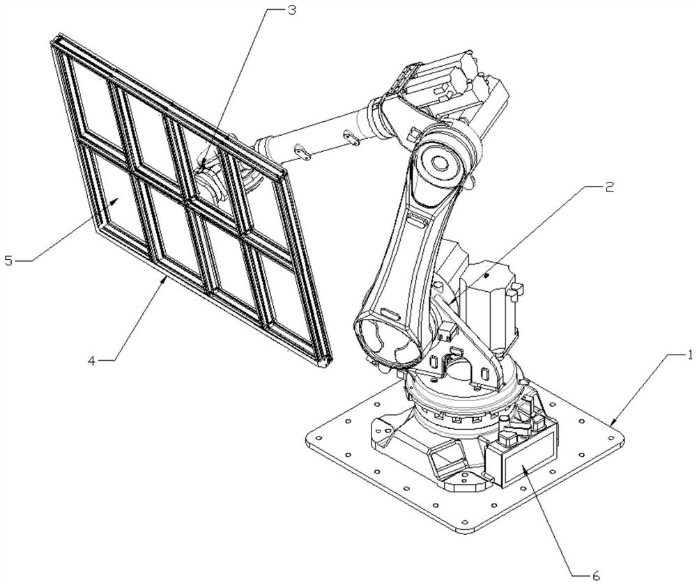
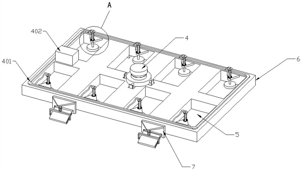
[0032] see Figure 1-5 As shown, this embodiment is a grabbing device for glass multi-station artificial split processing, including a base 1, a mechanical arm 2 is connected to the top of the base 1, and an assembly platform 3 is connected to the movable end of the mechanical arm 2 , the lower end of the assembly table 3 is equipped with a profile frame 4, and several groups of through grooves 5 are opened in the profile frame 4, and several groups of through grooves 5 are arranged in a rectangular array. The top of the base 1 is connected with a PLC controller 6, and the mechanical arm 2 is electrically connected to the PLC controller 6 .
[0033] A grasping method for glass multi-station artificial slivers processing, comprising the following steps:
[0034] S1. The base 1 is fixed on the ground of the working area, and the profile frame 4 is installed on the lower end of the assembly table 3;
[0035] S2, the PLC controller 6 controls the operation of the mechanical arm ...
Embodiment 2
[0040] see Figure 1-3As shown, this embodiment is a grabbing device for glass multi-station artificial split processing, including a base 1, a mechanical arm 2 is connected to the top of the base 1, and an assembly platform 3 is connected to the movable end of the mechanical arm 2 , the lower end of the assembly table 3 is equipped with a profile frame 4, and several groups of through grooves 5 are opened in the profile frame 4, and several groups of through grooves 5 are arranged in a rectangular array. The top of the base 1 is connected with a PLC controller 6, and the mechanical arm 2 is electrically connected to the PLC controller 6 .
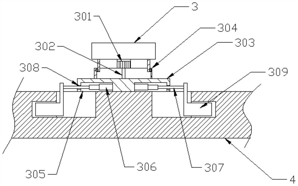
[0041] The center of the bottom of the assembly table 3 is connected with a steering motor 301, the output end of the bottom of the steering motor 301 is connected with a steering shaft 302, the bottom of the steering shaft 302 is connected with a round table 303, and a slewing bearing 304 is connected between the round table 303 and the a...
Embodiment 3
[0046] see Figure 1-5 As shown, on the basis of Embodiment 1, extension plates 7 are connected to the front and rear side walls of the profile frame 4, the lower end of the extension plate 7 is rotatably connected to a rotating shaft 701, and the outer wall of the rotating shaft 701 is connected to a folding plate 702. A guide groove 703 is opened on the plate 702, and a slide block 704 is slidably connected in the guide groove 703. The outer wall of the slide block 704 is hinged with a U-shaped bar 705, and the upper end of the U-shaped bar 705 is connected with an electric push rod 706. A positioning block 707 is connected to the top, and the positioning block 707 is fixedly connected to the outer wall of the extension plate 7. A tension spring 708 is connected between the positioning block 707 and the U-shaped bar 705, and the electric push rod 706 is electrically connected to the PLC controller 6.
[0047] The inner wall of the through groove 5 is connected with a fixed p...
PUM
 Abstract
Description
Claims
Application Information
 - R&D
- Intellectual Property
- Life Sciences
- Materials
- Tech Scout
- Unparalleled Data Quality
- Higher Quality Content
- 60% Fewer Hallucinations
Browse by: Latest US Patents, China's latest patents, Technical Efficacy Thesaurus, Application Domain, Technology Topic, Popular Technical Reports.
© 2025 PatSnap. All rights reserved.Legal|Privacy policy|Modern Slavery Act Transparency Statement|Sitemap|About US| Contact US: help@patsnap.com


