Fluid reservoir assembly

a reservoir and fluid technology, applied in the direction of liquid handling, crankcase compression engine lubrication, caps, etc., can solve the problems of difficult to grasp the polymer detent device, difficult to draw the plug base tight against the outer surface, etc., to increase the ease and efficiency of fluid maintenance, simple mechanical

Active Publication Date: 2008-06-12
BASF AG
View PDF11 Cites 34 Cited by
  • Summary
  • Abstract
  • Description
  • Claims
  • Application Information

AI Technical Summary

Benefits of technology

[0009]Accordingly, the subject invention provides a fluid reservoir assembly that is easily moved between the open position and the closed position by hand, without the use of a tool, due to the simple mechanical interaction between the ramps and the wings. Hand operation of the plug increases the ease and efficiency of fluid maintenance. The fluid reservoir assembly is also especially well suited for manufacture from a polymer material because of the simple geometric design configuration of the ramps and wings. A polymer fluid reservoir assembly reduces production costs and the weight of the fluid reservoir assembly.

Problems solved by technology

However, drawing the base of the plug tight against the outer surface is difficult as the clamping member tends to unintentionally rotate with the shaft, thereby not advancing nor retreating along the central axis of the shaft relative to the base.
However, the polymer detent device is sometimes difficult to grasp and is weakened by repetitive flexing while being removed.

Method used


Image

  • Fluid reservoir assembly
  • Fluid reservoir assembly
  • Fluid reservoir assembly

Examples


first embodiment

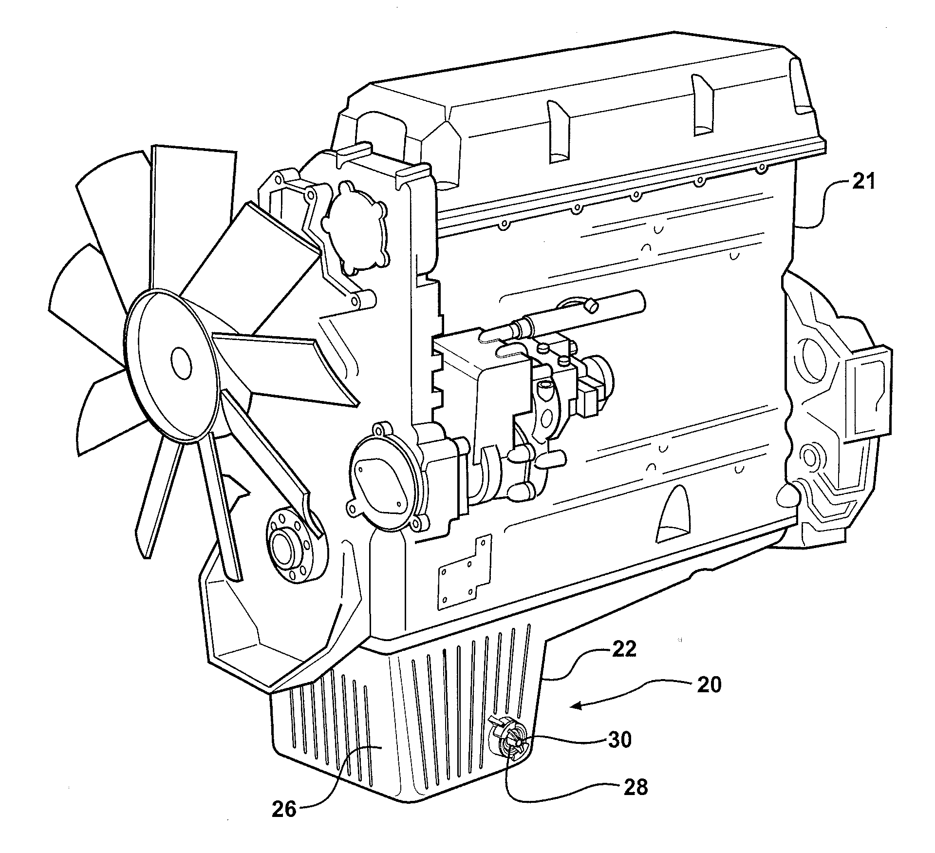
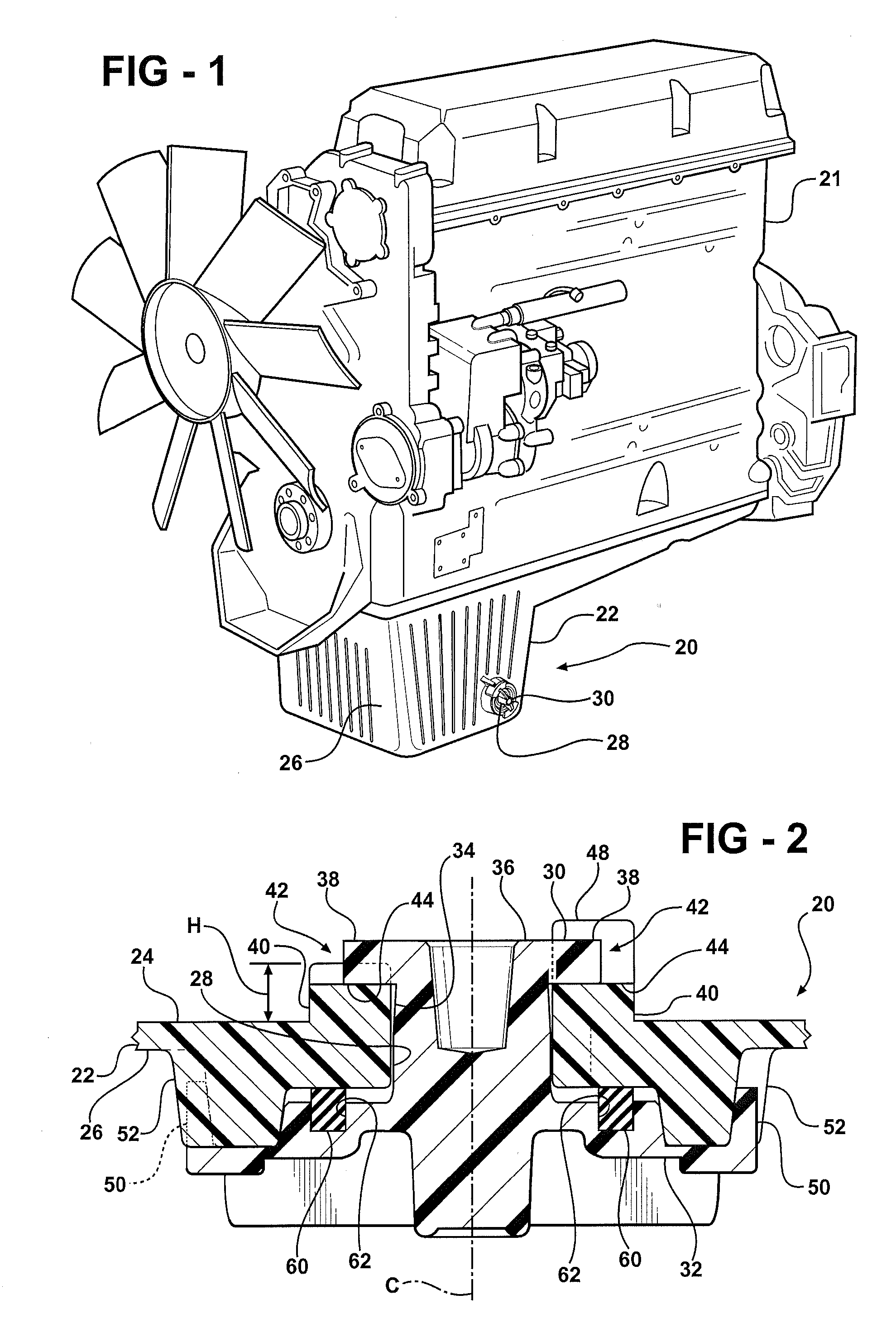
[0023]the fluid reservoir assembly 20 comprises a pan 22. Referring also to FIG. 2, the pan 22 includes an inner surface 24 and an outer surface 26. The pan 22 defines a cavity for storing a fluid therein, and also defines a drain opening 28 extending through the pan 22. The drain opening 28 allows for removal of the fluid from the cavity as required. As the embodiment described herein is an oil pan 22 for an engine, the fluid includes a motor oil. However, it should be appreciated that the type of fluid will vary with the different embodiments of the subject invention.

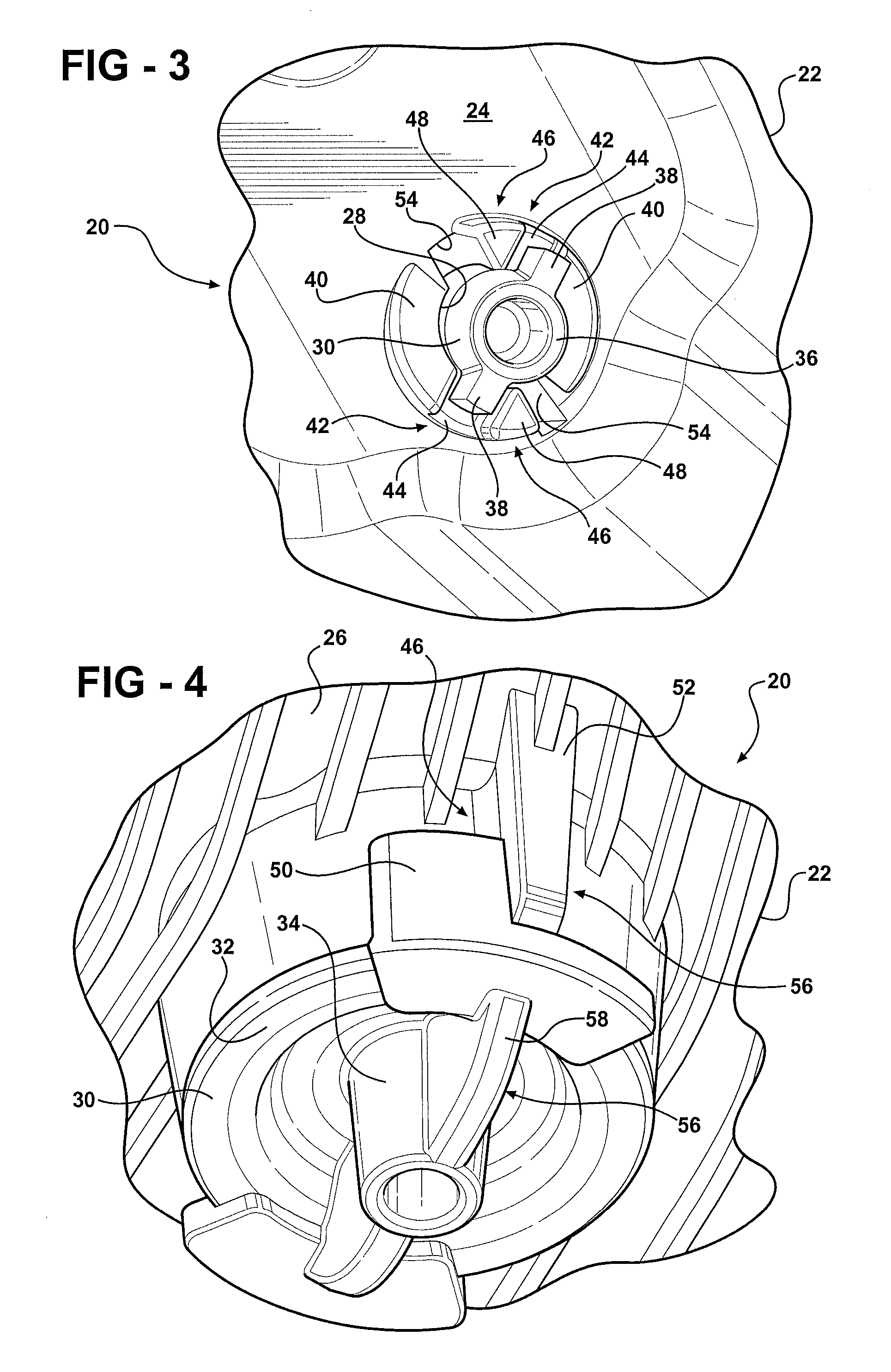
[0024]A plug 30 is disposed within the drain opening 28. The plug 30 is rotatably moveable between a closed position prohibiting fluid flow through the drain opening 28, and an open position permitting fluid flow through the drain opening 28. As best shown in FIG. 4, the plug 30 includes an aesthetic design to impart the impression of “finger-tight” operation, i.e., the plug 30 is to be manually rotated by hand withou...

second embodiment

[0032]The reservoir assembly 20 further comprises a stop 46. The stop 46 prevents rotation of the plug 30 in the first direction past the closed position. Preferably, and as shown in FIG. 3, the stop 46 includes a block 48 disposed on the inner surface 24 of the pan 22 adjacent each of the recesses 44 in each of the ramps 40. The blocks 48 abut the wings 38 when the plug 30 is in the closed position to prevent rotation of the wings 38 past the recess 44. However, it should be appreciated that the stop 46 need not include the blocks 48, and that the stop 46 may include another embodiment as described below or be incorporated into the lock mechanism such as shown in the fluid reservoir assembly 220 described below. Referring back to FIG. 4, the stop 46 may include, independently of or in combination with the blocks 48, a tab 50 attached to the plug 30 and a wall 52 disposed on the outer surface 26 of the pan 22 to abut the tab 50 when the plug 30 is in the closed position. The tab 50 ...

fourth embodiment

[0044]the fluid reservoir assembly 420 incorporates an internal fluid removal mechanism 480 for removing the fluid from with in the pan 422 without fully removing the plug 430 from the drain opening 428. The fluid removal mechanism 480 includes a passageway 481 extending through the shaft 434 of the plug 430. The passageway 481 includes a first portion 482, preferably concentric with the central axis C. The first portion 482 extends partially into the shaft 434 of the plug 430, from the base 432 toward the distal end 436 of the plug 430. The first portion 482 defines a fluid exit 484 at the base 432 of the plug 430. The passageway 481 further includes a second portion 486, which is in fluid communication with the first portion 482 and extends transverse to the central axis C to an outer edge of the shaft 434. The second portion 486 defines a fluid entrance 488, so that the fluid may enter through the fluid entrance 488 and flow through the second portion 486 of the passageway 481 an...


PUM


Abstract

A fluid reservoir assembly having a pan defining a drain opening and a plug disposed therein is disclosed. The pan includes a pair of ramps disposed on an inner surface thereof adjacent the drain opening. The plug includes a pair of wings in engagement with the ramps. The ramps increase in height relative to the inner surface of the pan along a first direction of rotation about the central axis. The plug is drawn into sealing engagement with an outer surface of the pan by rotating the plug in the first direction of rotation about the central axis thereby moving the wings up the ramps. The pan includes at least one stop to prevent over-rotation of the plug. The ramps define a recess to secure the wings in a closed position.

Description

CROSS REFERENCE TO RELATED APPLICATION[0001]This application claims the benefit of U.S. provisional patent application Ser. No. 60 / 868,804, filed on Dec. 6, 2006, the advantages and disclosure of which are hereby incorporated by reference.BACKGROUND OF THE INVENTION[0002]1. Field of the Invention[0003]The subject invention generally relates to a fluid reservoir assembly for storing a fluid therein.[0004]2. Description of the Related Art[0005]Fluid reservoir assemblies, typified by an oil pan for an engine, include a pan for storing a fluid therein. The pan includes an inner surface and an outer surface and defines a drain opening. To prevent fluid leakage, a plug is in sealing engagement with the outer surface of the pan. The plug includes a base and a shaft extending from the base through the drain opening along a central axis. Typically, the shaft of the plug is in threaded engagement with the pan, thereby attaching the plug to the pan. In such configurations, both the pan and the...

Claims


Application Information

Patent Timeline
Patent Type & Authority Applications(United States)
IPC IPC(8): F16N31/00F01M11/04
CPCF01M11/0408F01M2011/0425F01M2011/0416
Inventor SCHLICKER, SCOTT C.BALLOU, RAYMOND J.LEE, CHUL S.
Owner BASF AG
Why Eureka
Try Eureka