Audio recording system

Inactive Publication Date: 2007-11-29
ROKE MANOR RES LTD
View PDF5 Cites 30 Cited by
  • Summary
  • Abstract
  • Description
  • Claims
  • Application Information

AI Technical Summary

Benefits of technology

[0013] This improves ease of ar

Problems solved by technology

There are many situations in the broadcasting industry where it is difficult, or impossible to place a microphone close to the sources of sound that are of interest.
For example in the coverage of many sports events it is impossible to place a microphone close to the players.
These microphones have a number of limitations including the fact that t

Method used


Image

  • Audio recording system
  • Audio recording system
  • Audio recording system

Examples


Example

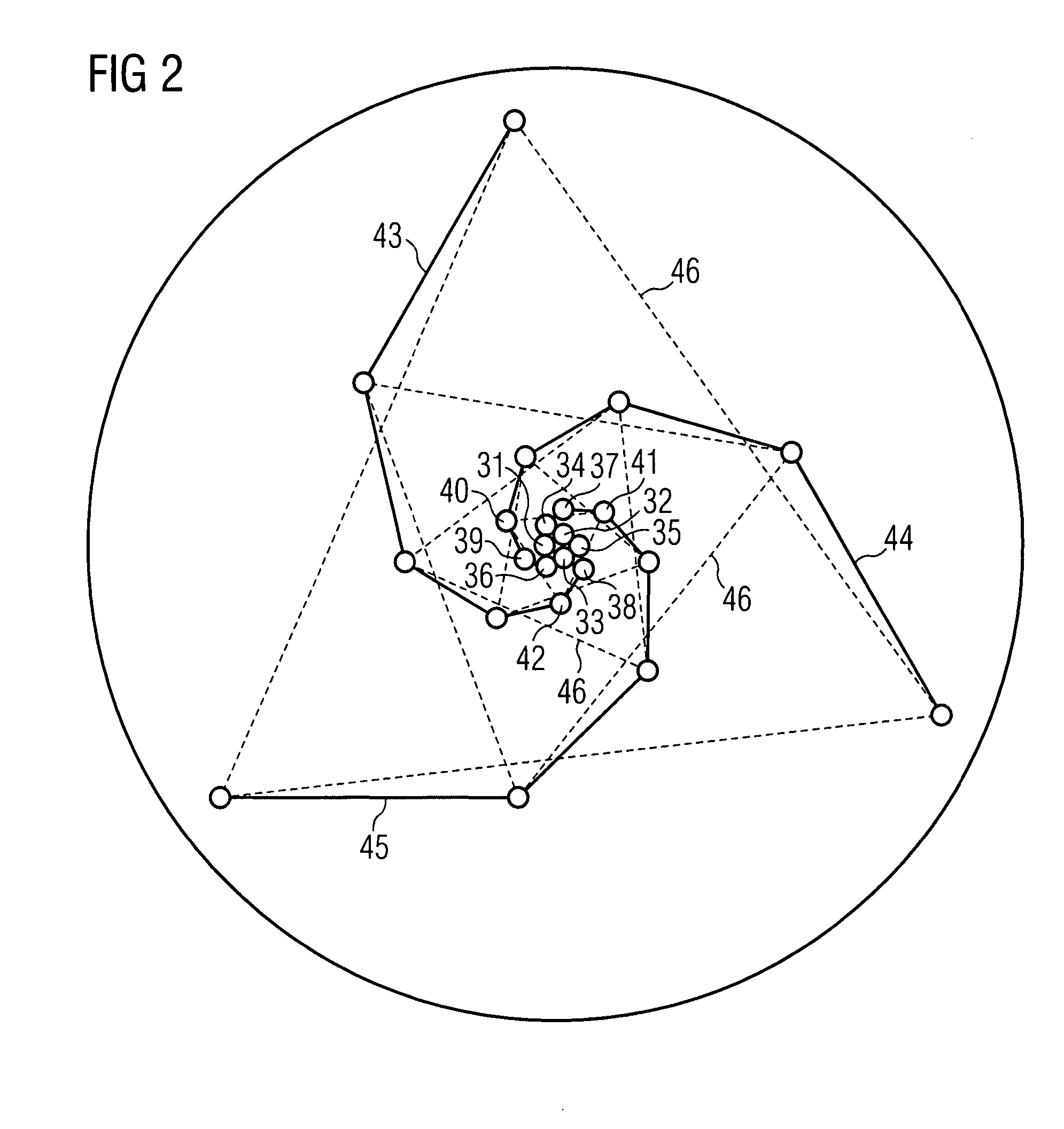
[0019] For the purpose of this application the term logarithmic spiral refers to an arrangement of microphones in a plane in which the density of microphones is greatest near the centre, and becomes progressively lower near the periphery.

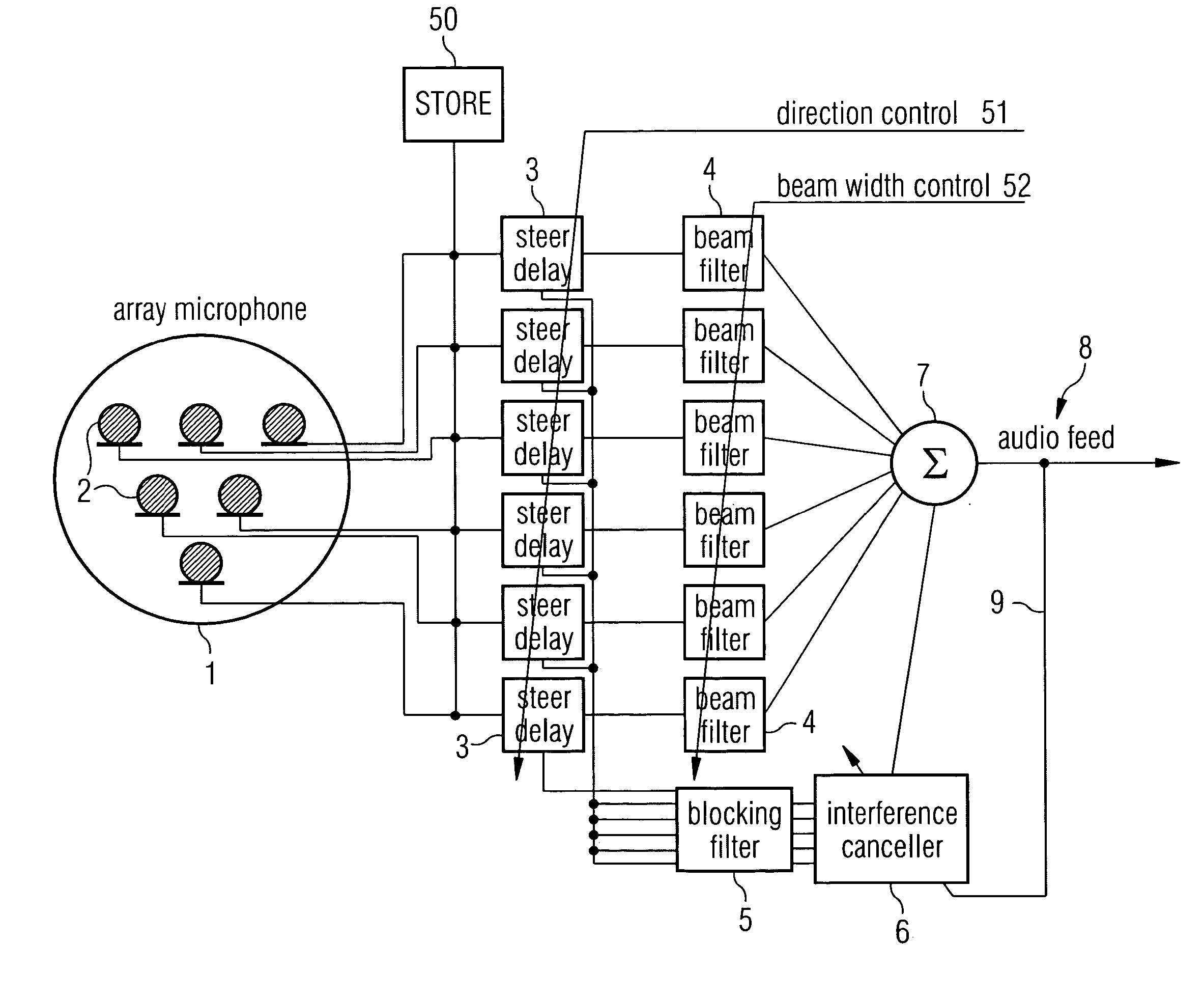
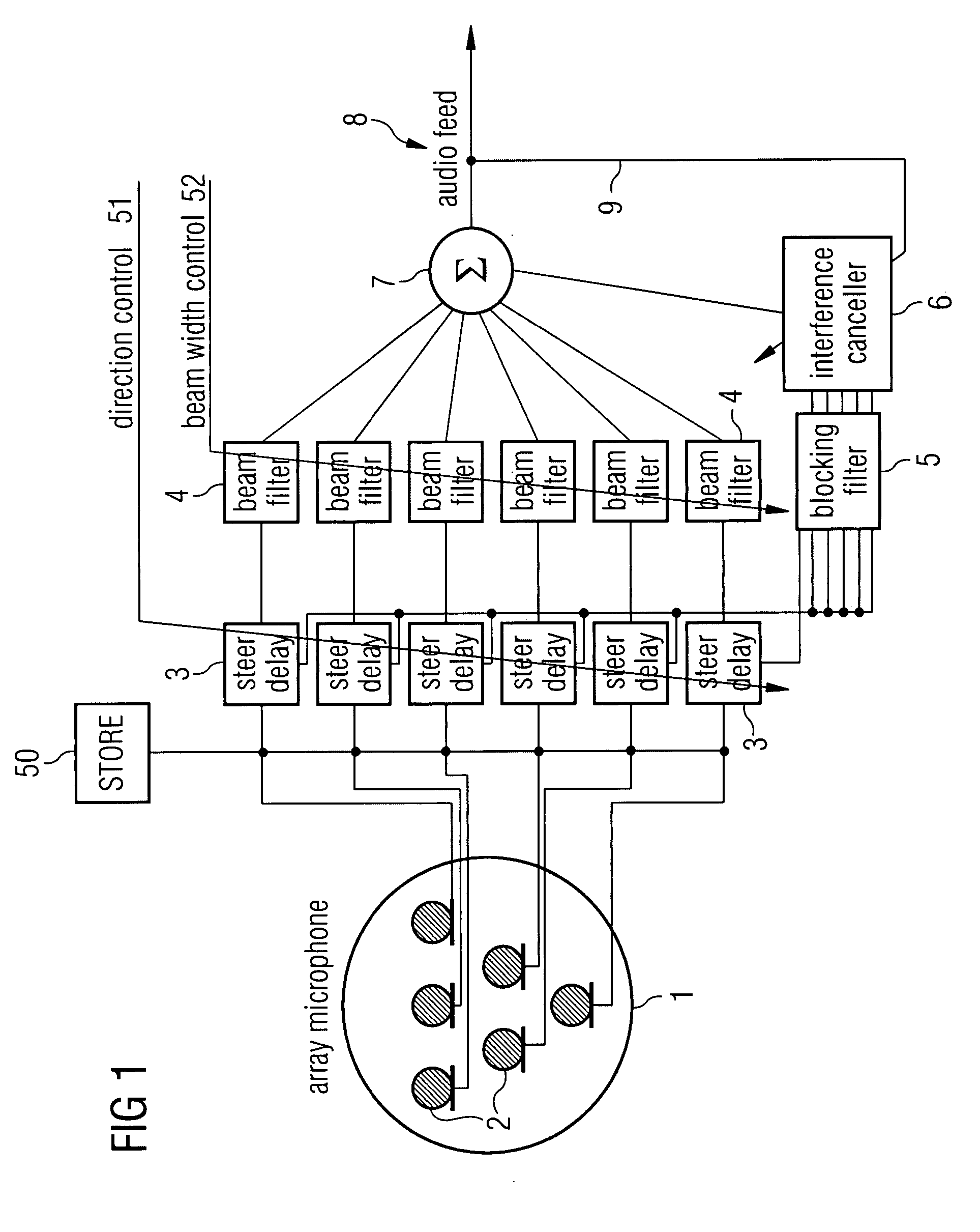
[0020] The present invention provides an array microphone which overcomes the problems of the prior art type and provides a very versatile tool for broadcast applications. Using audio recording technology, it is possible to record large numbers of audio channels to hard disk at low cost and with high fidelity. This allows the post processing of signals from a large scale array of microphones to isolate the audio of interest.

[0021] Microphone arrays have been used in hands-free telephony and teleconferencing and have also been proposed for hearing aid applications, amongst others. For such applications, the array microphones have relatively few elements, typically 4 to 8, and are consequently limited in their performance. There have also been acade...


PUM


Abstract

An audio recording system comprises an array of microphones and a processor module. The array is a logarithmic spiral array in which the minimum distance between each microphone and all others that lie closer to the centre is maximised. The processor module further comprises a beam direction control device and a beam width control device; whereby an audio target is isolated.

Description

BACKGROUND [0001] This invention relates to an audio recording system, in particular for recording a specific audio target some distance away. [0002] There are many situations in the broadcasting industry where it is difficult, or impossible to place a microphone close to the sources of sound that are of interest. For example in the coverage of many sports events it is impossible to place a microphone close to the players. In these circumstances the broadcaster will often use “gun” microphones, which are directional gradient microphones. In the case of football coverage, there may be as many as 12 gun microphones deployed around the pitch. These microphones have a number of limitations including the fact that they have relatively modest directivity (especially at low frequencies); they need to be physically moved to pick up sound in a different direction; they are very sensitive to wind noise; and there is strong frequency coloration of the output for sources off the main axis of se...

Claims


Application Information

Patent Timeline
IPC IPC(8): H04R3/00
CPCH04R1/406H04R3/005H04R2430/25H04R2201/401H04R25/407
Inventor LOCKHART, PETERMASSIE, STEVEN DAVIDTHOMAS, DEAN ROBERT
Owner ROKE MANOR RES LTD
Why Eureka
Try Eureka