
Dusting tool

a technology of dusting tool and edge area, which is applied in the field of dusting tools, can solve the problems of difficulty in cleaning curved surfaces and the inability to reach the edge areas of high-lying surfaces with difficulty, and achieve the effects of reducing the difficulty of cleaning curved surfaces, facilitating cleaning, and improving the effectiveness of cleaning uneven surfaces

Active Publication Date: 2008-10-16
CARL FREUDENBERG KG
View PDF5 Cites 3 Cited by
  • Summary
  • Abstract
  • Description
  • Claims
  • Application Information

AI Technical Summary

Benefits of technology

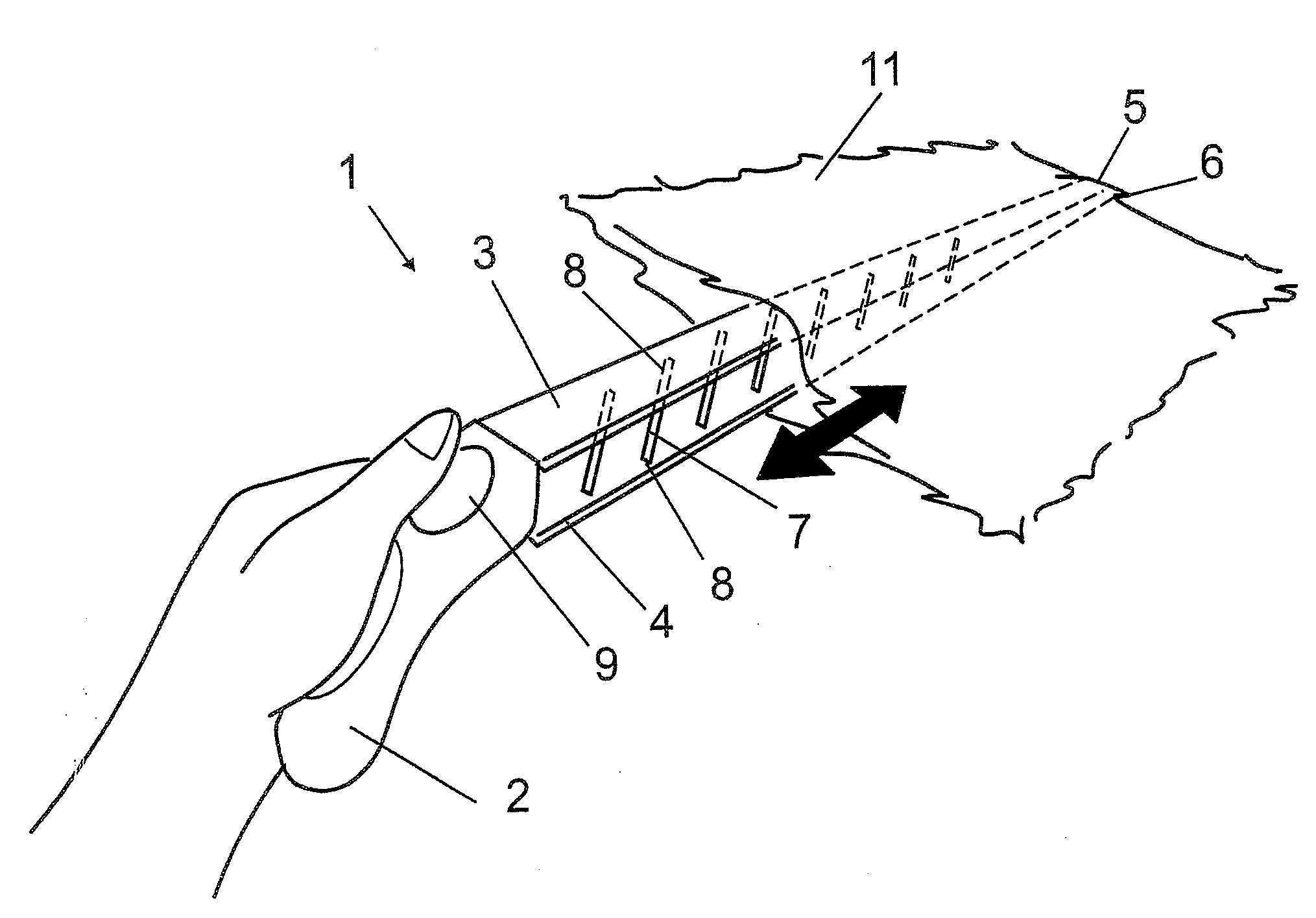
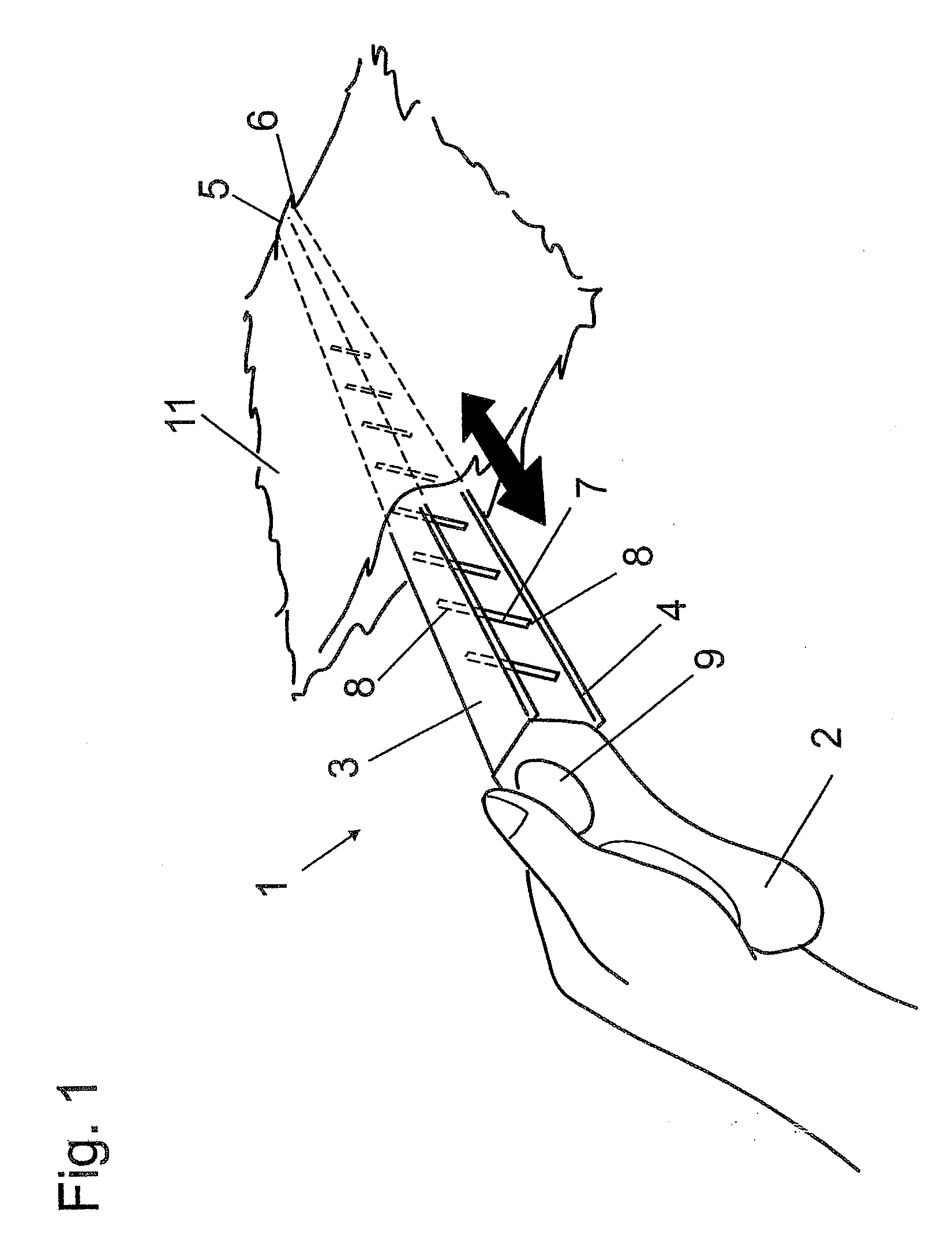
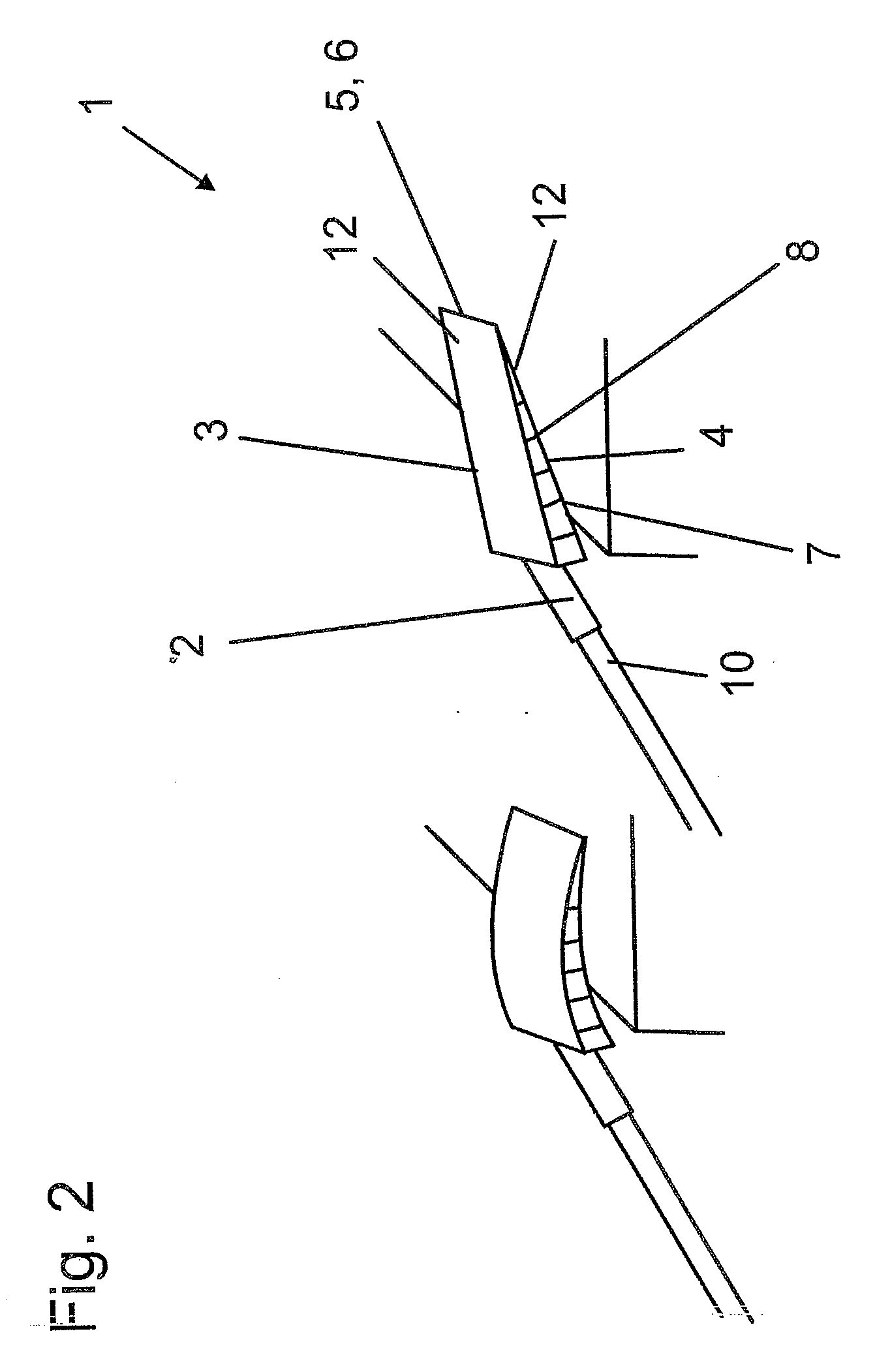
[0006]According to the present invention, the two bars are designed to be elastic, and the spacers are designed to be pressure- and / or tension-resistant so as to be able to transfer forces from one of the bars to the respective other bar. A first bar is elastically deformed as soon as it touches an uneven surface or as soon as it is elastically deflected in any other manner, and the deflection of the first bar is transferred to a second bar because the bars are connected to each other by means of the spacers. Both bars act as pressure and elastic bending bars. As a force is exerted on the first bar, said bar exerts a tensile force on the end of the second bar, which force tensions the first bar and deflects it in a bow-shaped manner. The second bar exerts a counterforce to the tensile force, as a result of which the second bar is subjected to a compressive bending strain. The spacers prevent the middle portion of the second bar from moving away from the first bar a distance greater than predetermined by the length of the spacer so that the middle portion of the second bar cannot be deflected outwardly. This ensures a bowlike curvature of the bars and thus a superior cleaning efficiency on uneven or hard-to-reach or high-lying surfaces.
[0015]The bars can be designed so as to have a flat surface. This improves the cleaning efficiency of the dusting tool.

Problems solved by technology

The bars of dusting tools of this type have a rigid design, which makes it difficult to clean curved surfaces.
However, these dusting tools are again suitable only for cleaning even surfaces since the section of the dusting tool which holds the cleaning fibers has a rigid design and therefore is unable to conform to curved surfaces.
Furthermore, the edge areas of high-lying surfaces can only be reached with difficulty.

Method used


Image

  • Dusting tool
  • Dusting tool
  • Dusting tool

Examples


Embodiment Construction

[0020]FIG. 1 shows a dusting tool 1 for dry dusting the surfaces of objects. The dusting tool 1 comprises a handle 2 to which two bars 3, 4 are attached at a certain distance from each other. The free ends 5, 6 of the bars 3, 4 are connected to each other. Between the bars 3, 4, a number of spacers 7 are disposed, which spacers are connected to the bars 3, 4 by means of hinged supports in the form of film hinges 8. The bars 3, 4 and the spacers 7 are made of a plastic material, in this case of polypropylene, and both are made of the same material and are integrally formed in one piece. They are manufactured by means of the injection molding method. Disposed to handle 2 is an actuating device 9. In this particular embodiment, the actuating device 9 comprises a push button which can be actuated by the thumb of a user. By actuating the push button of the actuating device 9, the first bar 3 is lengthened and the second bar 4 is shortened at the same time, which causes the dusting tool 1...


PUM


Abstract

A dusting tool (1) with a handle (2) to which two bars (3, 4) are attached at a certain distance from each other, with the free ends (5, 6) of said bars (3, 4) being connected to each other and with a number of spacers (7) being disposed between said bars (3, 4).

Description

FIELD OF THE INVENTION[0001]The subject matter of the present invention relates to a dusting tool with a handle to which two bars are attached at a certain distance from each other.BACKGROUND OF THE INVENTION[0002]The subject matter of the present invention relates to a dusting tool with a handle to which two bars are attached at a certain distance from each other.[0003]Dusting tools of this type are known from DE 20 2004 004 793 U1. On the bars of dusting tools of this type, cleaning cloths having a plurality of fiber sections are mounted. For cleaning, the dusting tool is moved across the surfaces to be cleaned, and the dust particles are trapped in the fiber sections. The bars of dusting tools of this type have a rigid design, which makes it difficult to clean curved surfaces. In addition, dusting tools are known, to the handle of which a pole is attached, which makes it possible to reach higher-lying surfaces as well. However, these dusting tools are again suitable only for clea...

Claims


Application Information

Patent Timeline
Patent Type & Authority Applications(United States)
IPC IPC(8): A46B5/02A47L13/10
CPCA46B5/0075A46B7/02A46B2200/3026A47L13/38A47L13/42
Inventor DINGERT, UWE
Owner CARL FREUDENBERG KG
Learn More