Charged Particle Gun

a technology of charged particles and guns, applied in the direction of machines/engines, liquid/fluent solid measurements, nuclear engineering, etc., can solve the problems of both types of guns taking an appreciable amount of time and skill to align, and the electron beam can suffer from aberration and be misaligned with the optical axis, etc., to achieve the effect of increasing the complexity

Active Publication Date: 2008-10-16
NANOBEAM
View PDF4 Cites 1 Cited by
  • Summary
  • Abstract
  • Description
  • Claims
  • Application Information

AI Technical Summary

Problems solved by technology

If they are not properly aligned, the resulting electron beam can suffer from aberration and be misaligned with the optical axis.
Both types of gun take an appreciable amount o

Method used


Image

  • Charged Particle Gun
  • Charged Particle Gun
  • Charged Particle Gun

Examples


Embodiment Construction

[0025]Electron Gun 1

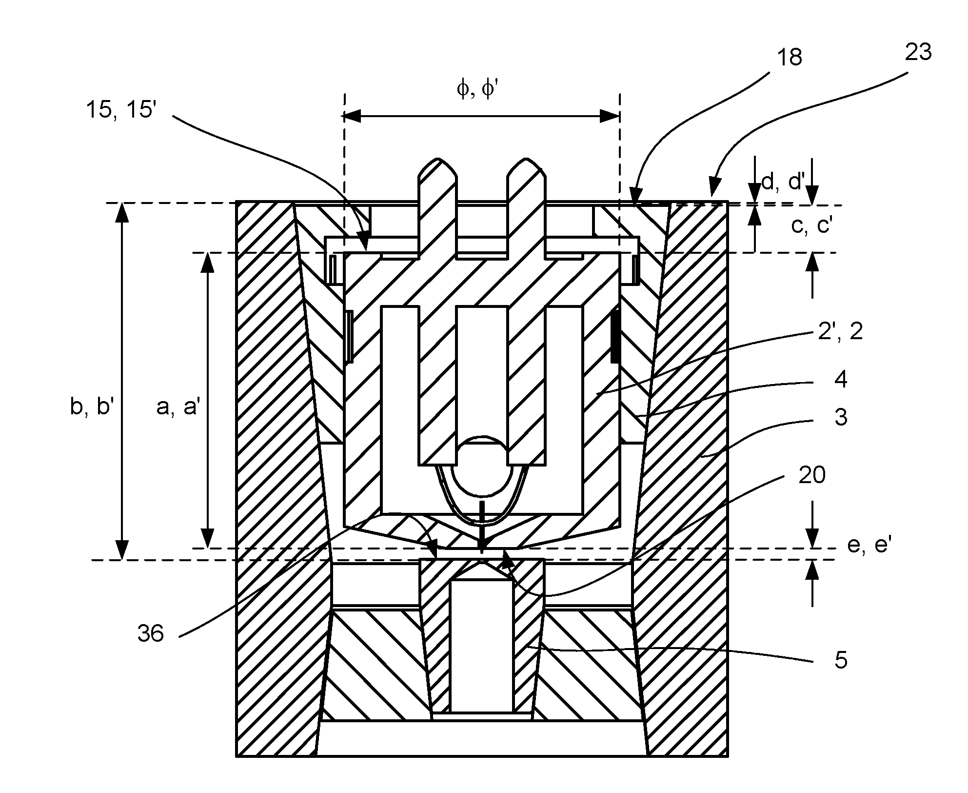
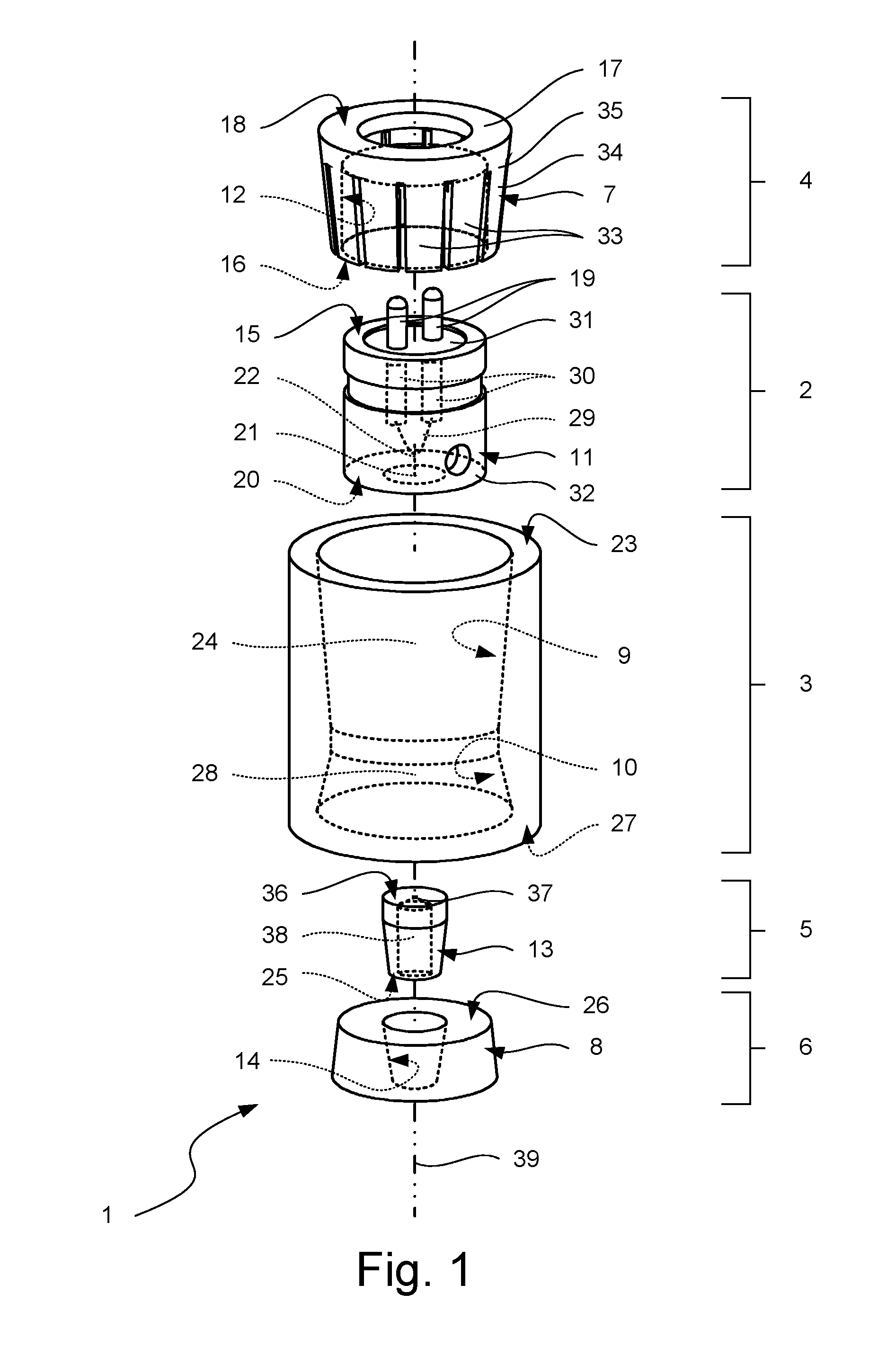
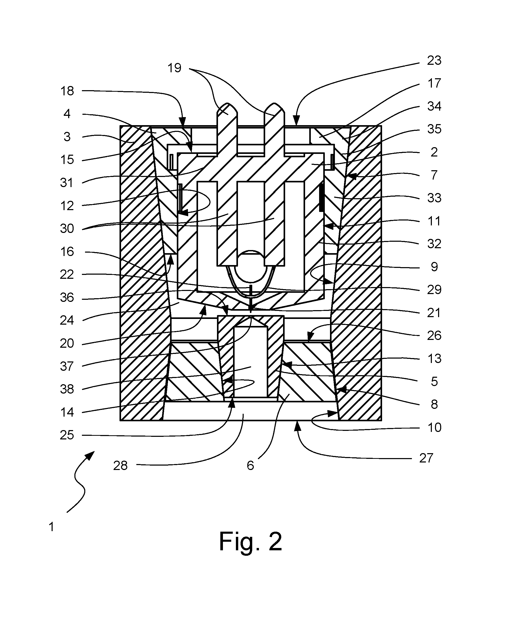
[0026]Referring to FIGS. 1 and 2, an embodiment of an electron gun 1 according to the present invention is shown. The electron gun 1 is a thermal field emission electron gun and comprises an emitter 2, a support 3, a first adaptor 4, an electrode 5 for extracting electrons and a second adaptor 6.

[0027]The first and second adaptors 4, 6 each serve as a plug and have respective plugging surfaces 7, 8. The support 3 is generally tubular and provides a pair of seats in the form of first and second seating surfaces 9, 10 for receiving the first and second adaptors 4, 6 respectively.

[0028]The emitter 2 serves as an insert having an outer surface 11 and the first adaptor 4 provides a slot in the form of an inner surface 12 for receiving the emitter 2.

[0029]The electrode 5 serves as a plug and has a plugging surface 13. The second adaptor 6 provides a seat in the form of a seating surface 14 for receiving the electrode 5.

[0030]A first end 15 of the emitter 2 is inserted ...


PUM


Abstract

An electron gun (1) includes an emitter (2), a tubular support (3) and an adaptor (4) for receiving the emitter. The adaptor includes a tapered plugging surface (7) and the tubular support includes a correspondingly tapered seating surface (9) for receiving the plugging surface. The plugging surface and seating surface have conical profiles which help to position the adaptor concentrically with the support.

Description

FIELD OF THE INVENTION [0001]The present invention relates to charged particle gun, particularly, but not exclusively an electron gun for use in an electron beam lithography system.BACKGROUND ART [0002]A cold field emission electron gun or a thermal field emission electron gun typically comprises a tip having a radius of about 1 μm or less and an electrode with an aperture having a diameter of about 300-700 μm. If a high enough bias is applied between the tip and the electrode, then a sufficiently high electric field is generated at the tip to extract electrons from it to produce an electron beam.[0003]The tip and the aperture need to be carefully laterally aligned and vertically spaced apart. If they are not properly aligned, the resulting electron beam can suffer from aberration and be misaligned with the optical axis. If they are not properly spaced, then extraction will not occur at workable voltages.[0004]The tip is provided in a unit called an emitter which can be obtained com...

Claims


Application Information

Patent Timeline
IPC IPC(8): H01J3/02H01J1/16H01J1/18H01J37/06H01J37/065H01J37/067
CPCH01J1/16H01J1/18H01J3/027H01J37/065H01J37/067H01J3/02H01J1/13H01J37/06
Inventor ZHANG, TAO
Owner NANOBEAM
Why Eureka
Try Eureka