Component inspection imaging apparatus structure

a technology of component inspection and imaging apparatus, which is applied in the direction of instruments, measurement devices, computing, etc., can solve the problems of inability to identify defects, inability to definitely identify the quality of the inspection component, and the drawback of conventional component inspection imaging apparatus, so as to enhance the accuracy and integrity of a component inspection

Inactive Publication Date: 2008-10-16
WU CHUN NAN
View PDF6 Cites 17 Cited by
  • Summary
  • Abstract
  • Description
  • Claims
  • Application Information

AI Technical Summary

Benefits of technology

[0005]Therefore, it is a primary objective of the present invention to provide an improved component inspection imaging apparatus structure for enhancing the accuracy and integrity of a component inspection.

Problems solved by technology

1. A conventional component inspection imaging apparatus as shown in FIGS. 1 and 2 includes an image capturing device 20a installed to a lateral side of an inspecting component 10a, such that the image capturing device 20a can inspect the image on one side of the inspecting component 10A only, and such conventional component inspection imaging apparatus has the drawback of unable to definitely identify the quality of the inspecting component.
2. Another conventional component inspection imaging apparatus as shown in FIGS. 3 and 4 includes an image capturing device 20b installed on the top of an inspecting component 10b, such that the image capturing device 20b can capture the image of the top surface of the inspecting component 10b, and thus having the drawback of unable to identify any defect occurred at a position around the top of the inspecting component 10b.

Method used


Image

  • Component inspection imaging apparatus structure
  • Component inspection imaging apparatus structure
  • Component inspection imaging apparatus structure

Examples


Embodiment Construction

[0020]The present invention will now be described in more detail hereinafter with reference to the accompanying drawings that show various embodiments of the invention.

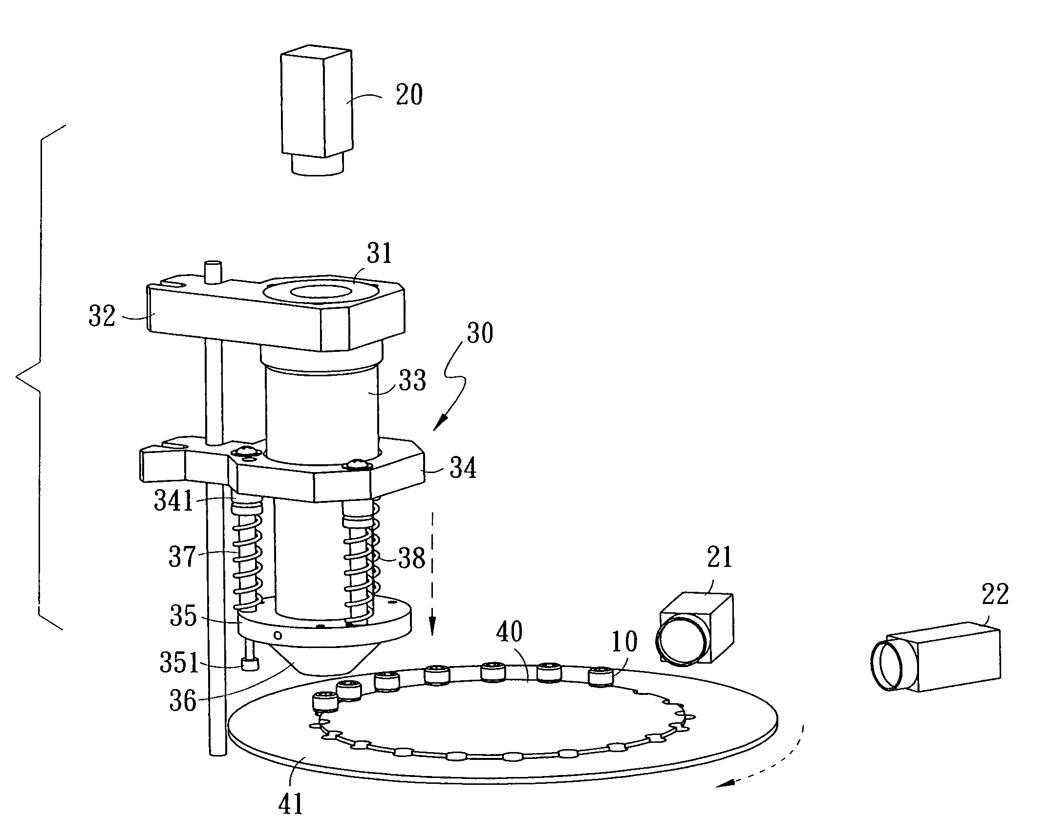
[0021]Referring to FIGS. 5, 6A and 7, the improved component inspection imaging apparatus structure comprises a component inspection imaging apparatus 30, a component retaining turntable 40 and image capturing devices 20, 21, 22; wherein the component inspection imaging apparatus 30 is comprised of an annular light source 31, an extension tube fixing rack 32, an extension tube 33, a mirror extending rack 34, a mirror fixing rack 35, a conical mirror 36, a plurality of positioning pins 37 and a plurality of springs 38; wherein a mirror plane portion 361 is formed on the internal side of the conical mirror 36 for completely reflecting every angle of the inspecting component 10, and an angle defined by engaging both ends of the conical mirror 36 allows an image reflected from the internal side of the conical mirror 36 an...


PUM


Abstract

An improved component inspection imaging apparatus structure comprises a component inspection imaging apparatus, a component retaining turntable and a plurality of image capturing devices. The component inspection imaging apparatus comprises an extension tube fixing rack, an extension tube, a mirror extending rack, a mirror fixing rack and a conical mirror. A mirror plane portion is disposed on an internal side of the conical mirror, and an inspecting component is put onto the component retaining turntable and rotated under the component inspection imaging apparatus. The component inspection imaging apparatus covers the inspecting component for inspection. An image of the surrounding at the head of the inspecting component is formed at the mirror plane portion in the conical mirror. The image capturing device at the top of the component inspection imaging apparatus captures an image of the head of the inspecting component from top to bottom to determine a defective component quickly.

Description

FIELD OF THE INVENTION[0001]The present invention relates to an improved component inspection imaging apparatus structure, and more particularly to a component inspection image apparatus structure capable of inspecting a component more accurately and quickly by the principle of a mirror image.BACKGROUND OF THE INVENTION[0002]Most conventional component inspection imaging apparatuses are used for inspecting the quality of screws, but these component inspection imaging apparatuses still have the following shortcomings in their practical applications:[0003]1. A conventional component inspection imaging apparatus as shown in FIGS. 1 and 2 includes an image capturing device 20a installed to a lateral side of an inspecting component 10a, such that the image capturing device 20a can inspect the image on one side of the inspecting component 10A only, and such conventional component inspection imaging apparatus has the drawback of unable to definitely identify the quality of the inspecting c...

Claims


Application Information

Patent Timeline
Patent Type & Authority Applications(United States)
IPC IPC(8): G06K9/00
CPCG01B11/2425G01N21/952
Inventor WU, CHUN-NAN
Owner WU CHUN NAN
Why Eureka
Try Eureka