Imaging apparatus, method and program

a technology of imaging apparatus and program, which is applied in the field of imaging apparatus, method and program, can solve the problems of inability to synthesize images during capturing, difficult to capture images at the angle of view desired by users, and easy to form gaps between frames

Active Publication Date: 2008-10-16
FUJIFILM CORP
View PDF5 Cites 37 Cited by
  • Summary
  • Abstract
  • Description
  • Claims
  • Application Information

AI Technical Summary

Benefits of technology

[0027]The display can provide the user with a suggestion on how to record with a better composition even if the user is unfamiliar with the composition.

Problems solved by technology

In the Japanese Patent Application Laid-Open Nos. 2003-134371 and 2000-156818, however, it is unclear how images are superimposed between frames, a gap is apt to be formed between the frames and images may not be able to be synthesized during capturing.
In the Japanese Patent Application Laid-Open No. 11-69293, the area of a synthesized still picture is equal to an integral multiplication of a captured area, which makes it difficult to capture images at an angle of view desired by a user and record the images.

Method used


Image

  • Imaging apparatus, method and program
  • Imaging apparatus, method and program
  • Imaging apparatus, method and program

Examples


first embodiment

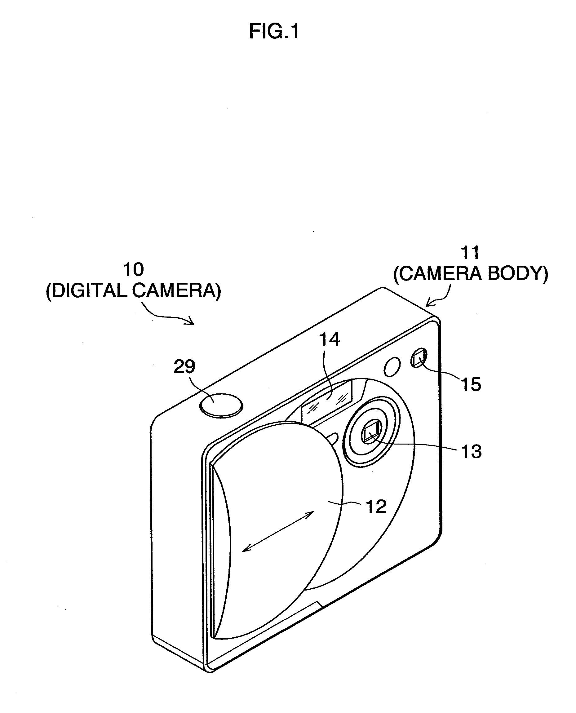
[0053]FIG. 1 is an external perspective view illustrating the configuration of front side of a digital camera. As illustrated in FIG. 1, a digital camera 10 is equipped with a lens barrier 12 which is slidable in the direction indicated by an arrow in the figure on the front side of a camera body 11. Sliding the lens barrier 12 to an open position illustrated in FIG. 1 exposes an imaging lens 13 and a flash light emitting unit 14 to the front face. The lens barrier 12 also acts as a power supply switch, turns on the power supply when it is slid to the open position to bring the camera into an imageable mode and turns off the power supply when it is slid to a shield position in which the imaging lens 13 and the flash light emitting unit 14 are shielded. A finder objective window 15 which forms an optical finder is provided on the front face of the camera body 11.

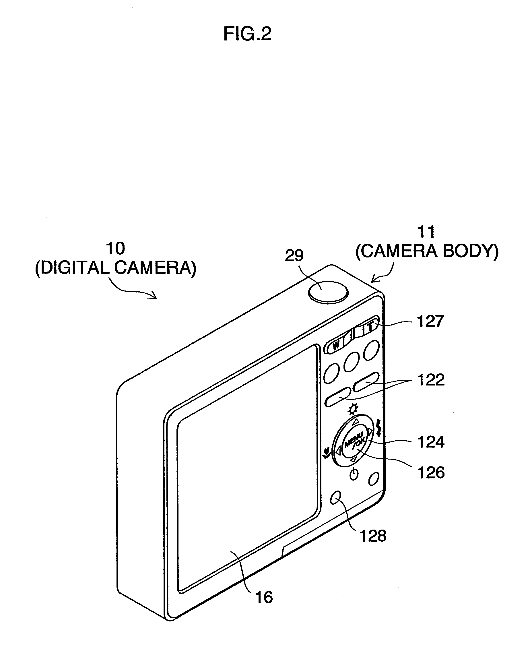
[0054]FIG. 2 is a rear elevation of the camera 10. A zoom switch 127 is disposed on the back face of the camera 10. Continu...

second embodiment

[0110]As described above, the entire shape of the synthesized image is not always perfect rectangular. For example, as illustrated in FIG. 14, a mosaic amorphous synthesized image E may be produced.

[0111]Such a synthesized image is partially expanded and displayed on the LCD panel 16 and the expanded portion is scrolled according to the specified scrolling direction by upward, downward, leftward, rightward and oblique depression of the cross key 124. For example, a portion of the area A in FIG. 14 is expanded and displayed, scrollable portions are the areas A1, A2 and A3. However, if only the area A is set to the display area, expanded and displayed, the user cannot realize that scrollable portions are the areas A1, A2 and A3. For this reason, the user may issue a useless instruction for the direction in which the areas cannot be scrolled.

[0112]Then, as illustrated in FIG. 15, superposing the icons of arrows D1 to D3 (alternatively, graphics or characters may be used) indicating the...


PUM


Abstract

An imaging apparatus displays and records any area in a synthesized image according to user's taste. The synthesized image is displayed based on the set display area and the record area is set to display the synthesized image, so that the display area is compared with the record area to enable easily confirming whether the actually acquired synthesized image satisfies the area desired by the user and assisting recording in an area where a better composition is provided even if the user is unfamiliar with the composition.

Description

BACKGROUND OF THE INVENTION[0001]1. Field of the Invention[0002]The present invention relates to an apparatus, method and program for synthesizing a plurality of images to produce one image and display it.[0003]2. Description of the Related Art[0004]According to Japanese Patent Application Laid-Open No. 2003-134371, a camera is capable of pick up images from the start to the end of shooting as one image, because it is provided with a calendar clock which obtains the time, an image pickup device which captures a plurality of object images for each of the time, a matching device which performs a pattern matching for searching a matched portion from among images before and after the plurality of captured images, an image extracting device which extracts part of the image in the longitudinal direction or part of the image in the transverse direction from the images subjected to the pattern matching and an image synthesizing device which joins together the part of the extracted image for...

Claims


Application Information

Patent Timeline
Patent Type & Authority Applications(United States)
IPC IPC(8): G06K9/36
CPCH04N5/23232H04N5/23238H04N5/23245H04N5/23293H04N5/272H04N23/50H04N23/951H04N23/667H04N23/698H04N23/635
Inventor ZHANG, YITONGMISAWA, TAKESHITAMARU, MASAYASUGIMOTO, MASAHIKONAKAMURA, TOMOKAZUOISHI, MAKOTO
Owner FUJIFILM CORP
Why Eureka
Try Eureka