Nasal cavity dilator

a dilator and nasal cavity technology, applied in the field of nasal cavity dilators, can solve the problems of increasing the risk of cardiac arrest, relatively high cost, and surgical procedures that are only temporarily successful, and achieve the effects of improving the safety of cardiac arres

Inactive Publication Date: 2006-11-16
ASAP BREATHEASSIST
View PDF11 Cites 30 Cited by
  • Summary
  • Abstract
  • Description
  • Claims
  • Application Information

AI Technical Summary

Benefits of technology

[0012] In accordance with the invention there is provided a controllably adjustable nasal cavity dilation device for controllably urging the cavity towards a dilated condition, the device including a body having a wall structure which is capable of expansion upon exertion of an applied force to the body; the body being shaped to enable insertion of the device within the cavity in a first condition to rest against internal walls of the nasal cavity wherein when the body is acted upon by an applied force the wall structure extends laterally of the body in a controlled manner within the cavity to exert a positive pressure against the internal walls thereby to dilate the cavity and control the passage of air there through.
[0013] The present invention differs from prior art devices in that the instant device can be inserted within a nasal cavity of a user in a non-compressed condition. Hence upon insertion of the device a wearer experiences substantially no discomfiture. Once the device is inserted within a nasal cavity the device can be adjusted in situ, in a controlled manner by the wearer, to tailor a desirable degree of expansion against nasal cavity walls and hence influence the flow of air and pressure applied to the walls to suit the users requirements. Unlike any prior art device the instant device enables expansion of separate nasal cavities independently particularly where a pair of nasal cavities is asymmetrical due to a deviated septum.

Problems solved by technology

People who are disposed to such conditions can be subject to feelings of general tiredness, shortness of breath, fatigue, sleep deprivation, snoring, and even sleep apnoea, which can increase the risks of cardiac arrest.
Apart from requiring a sufferer to endure invasive surgery and the relatively high costs associated therewith, it is documented that surgical procedures are only temporarily successful, sufferers requiring repeated surgery to obtain ongoing relief.
The problem with spray formulations, however, is that they often contain steroidal or vasoconstrictors active agents that cause side effects and can lead to a chronic addiction problem or withdrawal difficulties.
These types of devices involve complex designs that are very conspicuous on a wearer.
A problem associated with this type of approach is that the plaster is not aesthetically pleasing, and is limited by both the inherent resiliency of the plaster and its ability to exert a sufficient outward force to expand and maintain a nostril cavity in an open condition.
In addition the plaster requires painful removal that could result in the tearing of skin.
Also problems frequently arise in a nasal application when a wearer exhibits a deviated septum.
A curved septum often renders one nasal cavity a different shape and size to its neighbour and inhibits airflow through one side of the nose and can result in airflow blockage through one nostril.
Prior art devices, of the type disclosed in U.S. Pat. No. 5,895,409 that are insertable within the nasal cavity, suffer the drawback that if one dilator of a symmetrical pair, to be inserted, is of a sufficiently small size to enter one nostril then the remaining dilator of the pair is too small to be effective in dilating the other nostril.
Conversely, if one device of a symmetrical pair is sufficiently large to effectively dilate one nostril, its pair is often too large to be inserted in the other nostril.
This device confers a deal of discomfort for a wearer upon insertion because the device is generally larger than the corresponding orifice in which it is to inserted.
These type of dilators are very uncomfortable for a wearer and the force generated by the resilient plastic often causes irritation to the inside lining of the nose not to mention that the article is conspicuous.

Method used


Image

  • Nasal cavity dilator
  • Nasal cavity dilator
  • Nasal cavity dilator

Examples


Embodiment Construction

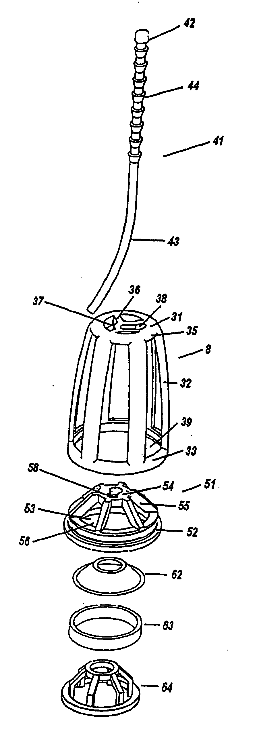
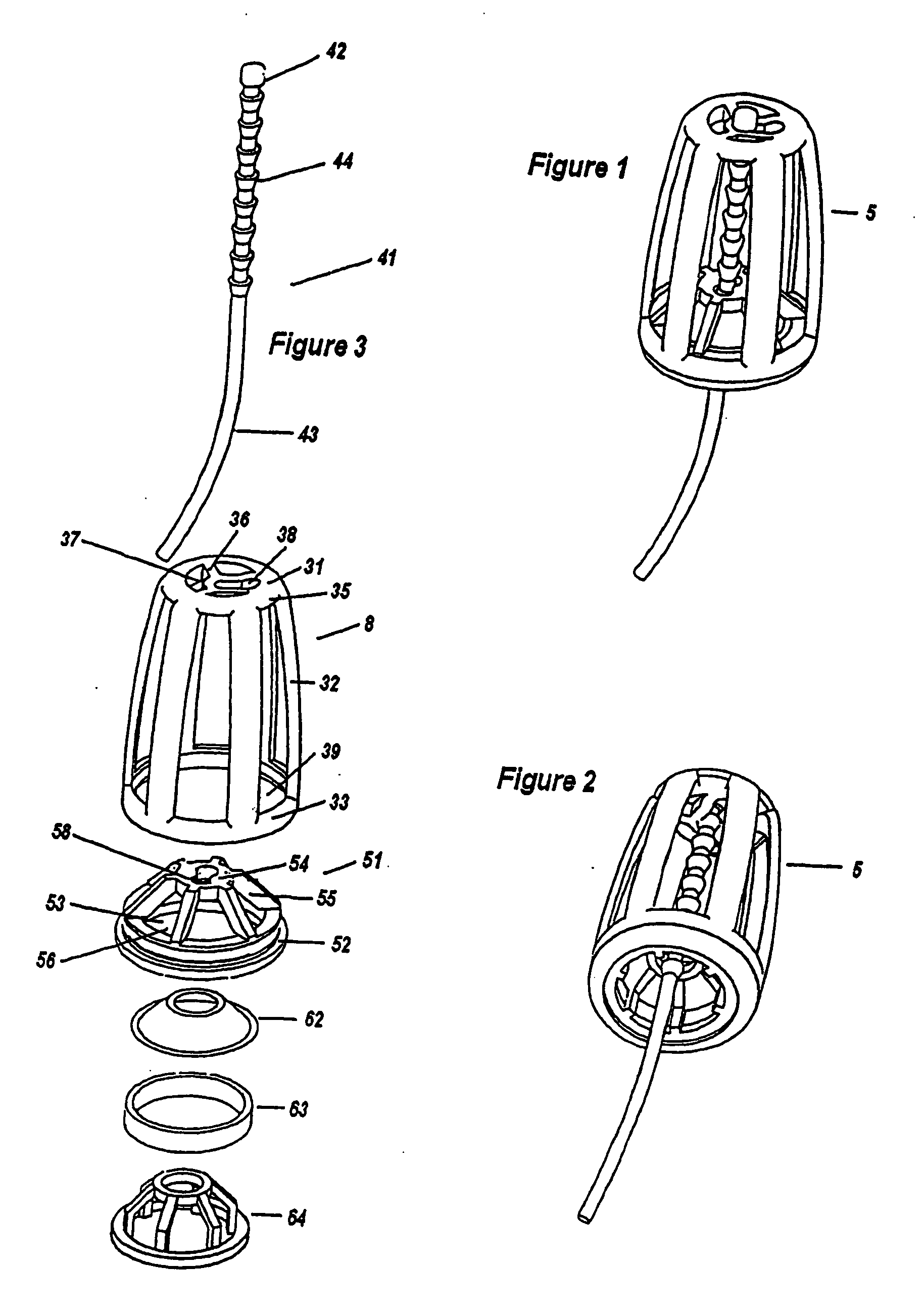
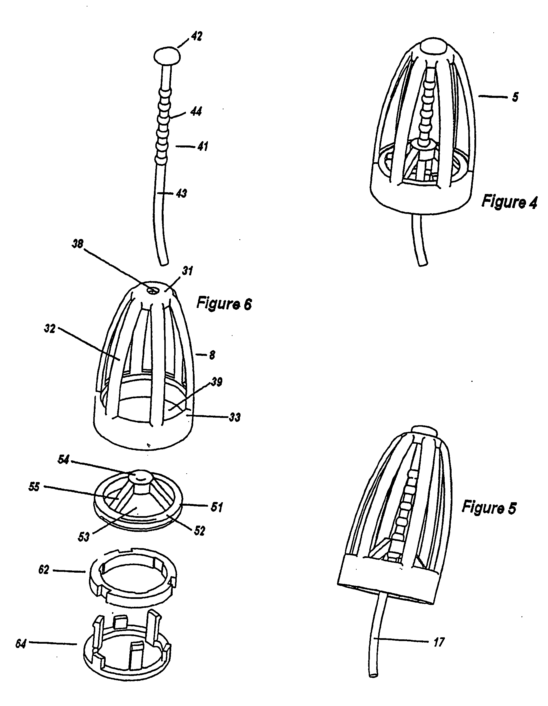
[0105] Referring to FIGS. 1, 2 and 3 there is shown a nasal dilation device (5) insertable within a body cavity such as the nose. The nasal cavity dilation device is for urging the cavity towards an open condition. The device has a body (8) with a flexible wall structure formed by a plurality of longitudinally extending elongated ribs (32) extending between a top frame (31) and a bottom frame (33). The top frame (31) has an outer circular collar (35) with inner radial like struts (36) providing flow through openings (37) and a shaped opening forming a mounting opening (38). The bottom frame (33) is a circular waistband with a plurality of elongated spaced ribs (32) connected to the collar (35) and the waist band (33). The ribs at least are made from flexible plastics so that the wall structure has variable geometry. The sizing of the device is such that it is insertable within the nasal cavity.

[0106] The nasal dilation device (5) further includes an expansion means comprising a con...


PUM


Abstract

An adjustable nasal cavity dilation device includes a first deformable body having a shape corresponding to the nasal cavity. Top and bottom frame ends of the body are interconnected by a flexible wall structure that undergoes deformation in response to movement of one frame end relative to the other. A releasable holding member includes a ring that engages the bottom frame end and an upstanding central member that engages the top frame end. The ring and the upstanding central member are coupled by a plurality of radial arms. The flexible wall structure is deformed and effective for urging against nasal cavity walls to increase air flow through the nasal passage when the top and bottom frame ends are maintained in a holding condition by the ring and the upstanding central member. The ring and radial arms define openings that permit passage of air into and out of the nasal cavity through the releasable holding member.

Description

CROSS-REFERENCE TO RELATED APPLICATIONS [0001] The present application in a continuation of co-pending U.S. application Ser. No. 10 / 631,415 entitled “Nasal Cavity Dilator”, filed Jul. 30, 2003.FIELD OF THE INVENTION [0002] The present invention relates to a device, which can be easily adjustable for insertion in a body cavity such as the nasal cavity of a person to dilate the cavity into variable states of dilation and / or to maintain the cavity in a predetermined dilated state. BACKGROUND OF THE INVENTION [0003] Snoring and general breathing dysfunctions are common ailments that affect a significant proportion of the world's population. People who are disposed to such conditions can be subject to feelings of general tiredness, shortness of breath, fatigue, sleep deprivation, snoring, and even sleep apnoea, which can increase the risks of cardiac arrest. [0004] Attempts have been made to address the above conditions. For instance one option available to sufferers involves a surgical ...

Claims


Application Information

Patent Timeline
Patent Type & Authority Applications(United States)
IPC IPC(8): A61B17/24A61M29/00A61F5/08
CPCA61B17/24A61B2017/248A61M29/00A61F5/56A61F5/08A61M15/08
Inventor MARYANKA, PAZ
Owner ASAP BREATHEASSIST
Why Eureka
Try Eureka