Rolling bearing device

a bearing device and rolling bearing technology, applied in the direction of bearings, shafts and bearings, bearings, etc., can solve the problems of poor rigidity and deformation, bearings are not firmly fixed, and the transmission noise occurs, so as to achieve excellent vibration damping performance and rigidity

Inactive Publication Date: 2008-10-16
JTEKT CORP
View PDF23 Cites 14 Cited by
  • Summary
  • Abstract
  • Description
  • Claims
  • Application Information

AI Technical Summary

Benefits of technology

[0006]An object of the invention is to provide a rolling bearing device provided with a vibration isolating member which is excellent in vibration damping performance and rigidity, and in which deterioration due to intrusion of oil or the like is unlikely to occur.

Problems solved by technology

The gear noise in the transmission occurs, when vibration is generated at an engaged position of the gear, and the generated vibration passes through a shaft and a bearing to resonate with a housing or surrounding members.
The vibration isolating shim and the vibration isolating cover employing resin have high vibration damping performance, but there is such a problem that they have poor rigidity and are likely to be deformed when they are used at high temperature.
For this reason, the bearing is unable to be firmly fixed, and engaging accuracy of the gears is liable to be deteriorated.
Particularly, in case of the bearing to be preloaded for use, such as a taper roller bearing and an angular ball bearing, the vibration isolating shim or the vibration isolating cover is pressurized, and so, lack of rigidity and deformation become a particular problem.
There is another problem that in the vibration isolating shim or the vibration isolating cover formed of resin, resin material is deteriorated when oil has intruded.
However, there is such a problem that they are inferior in vibration damping performance, as compared with the vibration isolating shim and cover formed of resin.

Method used


Image

  • Rolling bearing device
  • Rolling bearing device
  • Rolling bearing device

Examples


first embodiment

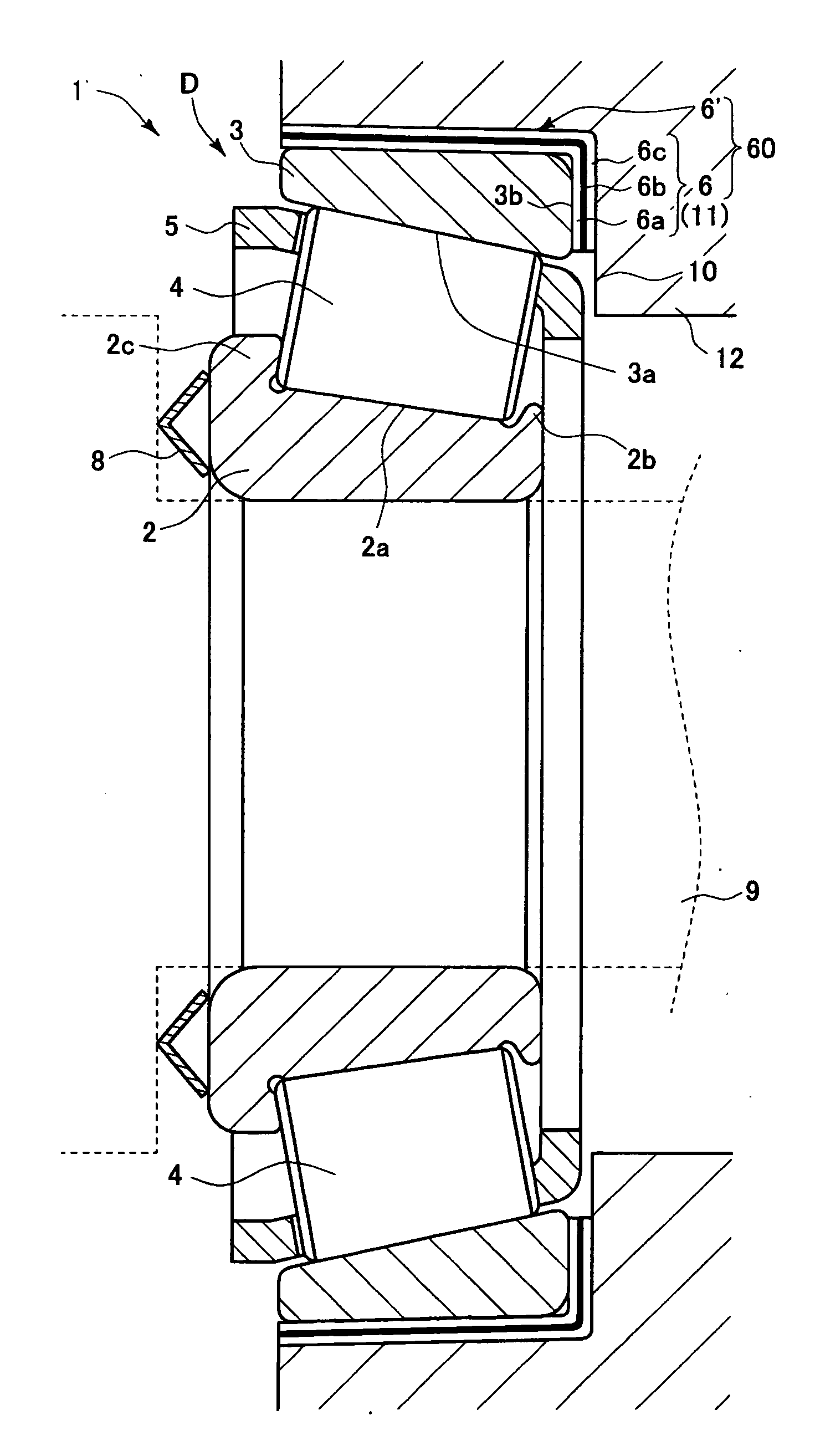
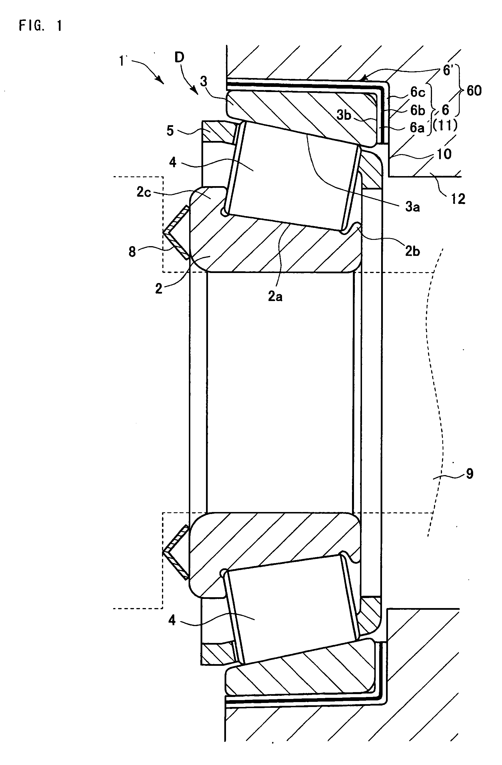
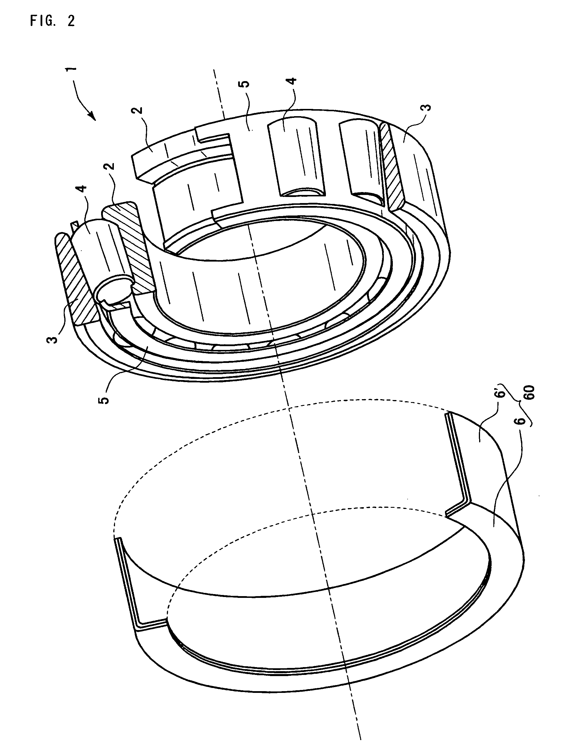
[0033]FIG. 1 is a vertical sectional view of a rolling bearing device according to a first embodiment of the invention, and FIG. 2 is an exploded perspective view of the same. As shown in the drawings, a rolling bearing 1 includes an inner ring 2 which is provided with a raceway surface 2a for a rolling element 4 on its outer peripheral surface, and an outer ring 3 which is provided with a raceway surface 3a for the rolling element 4 on its inner peripheral surface. The outer ring 3 is arranged in a concave part D which is formed in a fixing member 12 such as a transmission case so as not to rotate in a state preloaded in an axial direction toward the inner ring 2 by way of the rolling element 4, with the fixing member 12 at a bottom surface 10 of the concave part D.

[0034]In this embodiment, the rolling bearing 1 which is used in a gear driven type transmitting unit, such as a transmission unit for an automobile is a taper roller bearing using a taper roller as the rolling element 4...

second embodiment

[0044]Then, a second embodiment of the invention is shown in FIG. 4, and a longitudinal sectional view of the vibration isolating sleeve 60 in FIG. 4 is shown in an enlarged scale in FIG. 5. In this embodiment, resin layer sealed parts 7a, 7b in which, for the purpose of sealing the resin layer 6b, a pair of the metal layers 6a, 6c are directly brought into tight contact in a circumferential direction with each other at an inner peripheral edge of the vibration isolating part 6 in the radial direction, and at an end edge of the auxiliary vibration isolating part 6′ in the axial direction at a side not connected to the vibration isolating part 6 are respectively provided. Because the resin layer 6b is sealed in this manner, the problems such as deterioration of the resin layer 6b due to intrusion of the oil and decrease of rigidity due to overflow of the resin are unlikely to occur. More specifically, a pair of the metal layers 6a, 6c are caulked and press-fitted to each other in the...


PUM


Abstract

The rolling bearing includes an inner ring, and an outer ring which is arranged in a concave part which is formed in a fixing member so as not to rotate in a state preloaded in an axial direction toward the inner ring by way of a rolling element, with the fixing member at a bottom surface of the concave part. Moreover, a vibration isolating part formed of a laminated body including a pair of metal layers and a resin layer which is thinner than these metal layers and interposed between them is press clamped to be disposed between an end surface of the outer ring at a preloaded side in the axial direction and the bottom surface of the concave part, in such a manner that a direction of lamination may coincide with the axial direction.

Description

BACKGROUND OF THE INVENTION[0001]The present invention relates to a rolling bearing device.[0002]In recent years, developments for improving quietness of an automobile have been promoted. Among the developments, to decrease gear noise in a transmission is a matter to be developed which is particularly regarded as important. The gear noise in the transmission occurs, when vibration is generated at an engaged position of the gear, and the generated vibration passes through a shaft and a bearing to resonate with a housing or surrounding members.[0003]In order to solve this problem, an art of fitting a vibration isolating shim or a vibration isolating cover formed of resin or metal to an outer peripheral surface of the bearing has been known (JP-A-H07-145814 and JP-A-2004-108539, for example). Because the vibration transmitted from the bearing to the housing or the surrounding members is moderated by the vibration isolating shim or the vibration isolating cover, it is possible to decrea...

Claims


Application Information

Patent Timeline
Patent Type & Authority Applications(United States)
IPC IPC(8): F16C19/00
CPCF16C27/066F16C35/077F16C19/364
Inventor DODORO, HIROFUMINISHIMURA, KOMATSUGUITO, IKUO
Owner JTEKT CORP
Why Eureka
Try Eureka