Thermal control apparatus

a control apparatus and control technology, applied in the direction of indirect heat exchangers, light and heating apparatus, cosmonautic vehicles, etc., can solve the problems of inability to realize thermal design, structural complexity, heavy weight, etc., and achieve the effect of facilitating weight reduction and structural/mechanistic simplification

Inactive Publication Date: 2008-10-23
JAPAN AEROSPACE EXPLORATION AGENCY
View PDF0 Cites 29 Cited by
  • Summary
  • Abstract
  • Description
  • Claims
  • Application Information

AI Technical Summary

Benefits of technology

[0007]In view of the above conventional problems, it is an object of the present invention to provide a novel thermal control apparatus capable of facilitating wei

Problems solved by technology

However, in spacecrafts to be exposed to large environmental changes, such as moon/planetary probe vehicles, a power consumption of the heater will be unacceptably increased to cause difficulty in realizing thermal design.
The thermal louver is capable of passively coping with changes in thermal environment, whereas it involves problems, such as incapability of increasing an amount of heat dissipation, structural complexity and heavy weight.
The deployable radiator

Method used


Image

  • Thermal control apparatus
  • Thermal control apparatus
  • Thermal control apparatus

Examples


first embodiment

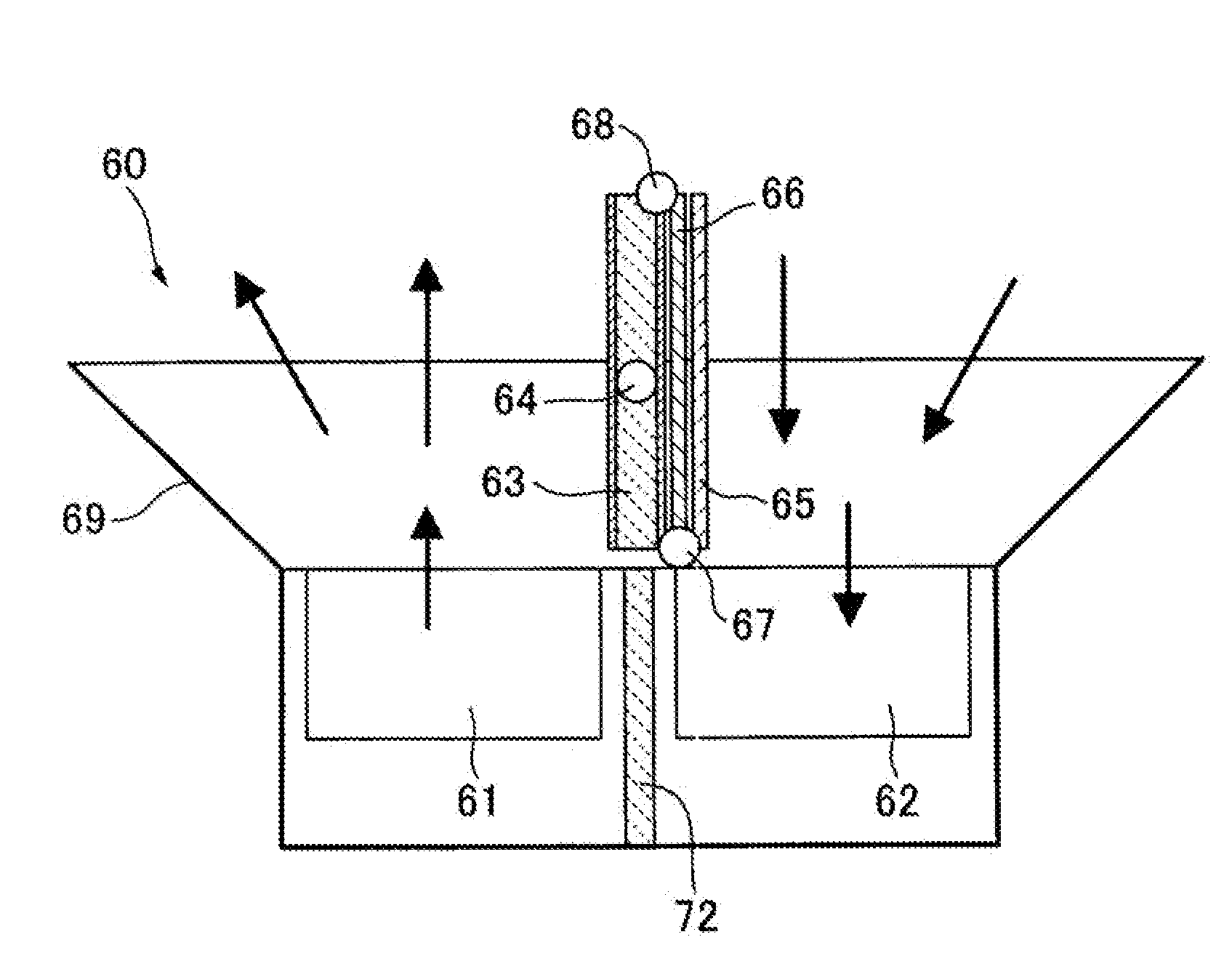
[0035]FIG. 1 is a sectional view showing a thermal control apparatus 10 according to a first embodiment of the present invention, wherein a left half thereof shows a state after a paddle of the thermal control apparatus is closed (i.e., retracted), and a right half thereof shows a state after the paddle is opened (i.e., deployed). The thermal control apparatus 10 according to the first embodiment is intended to be installed in a spacecraft, particularly in a small satellite. In FIG. 1, the reference numeral 1 indicates one of various on-board devices of a spacecraft, which are to be subjected to thermal control (hereinafter referred to as “target object”). The thermal control apparatus 10 comprises a base plate 15. In the first embodiment, the base plate 15 is formed as a part of a satellite structure.

[0036]As shown in FIG. 1, the thermal control apparatus 10 according to the first embodiment includes a pair of right and left deployable / retractable heat-exchange paddles 12b, 12a (he...

second embodiment

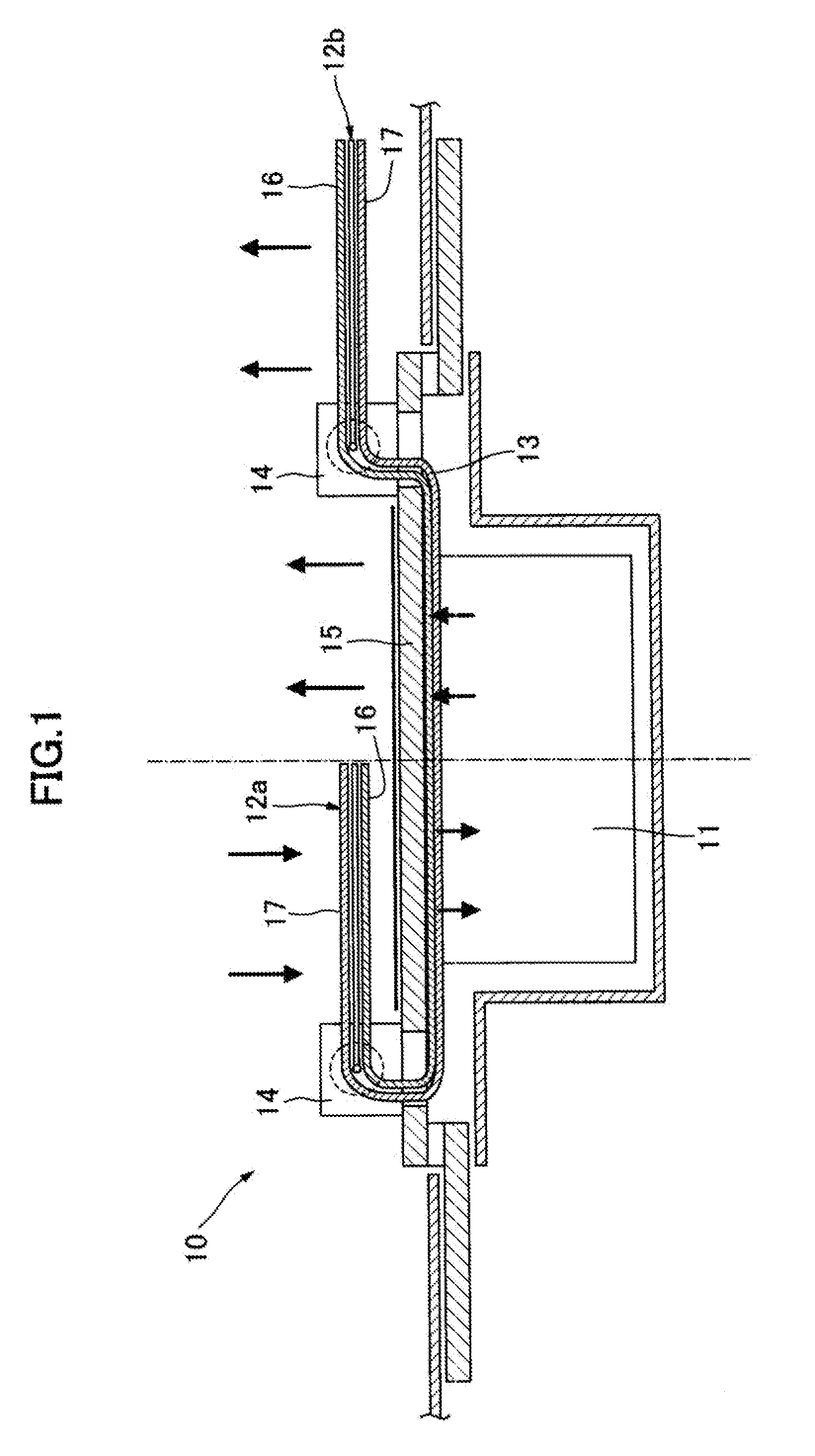
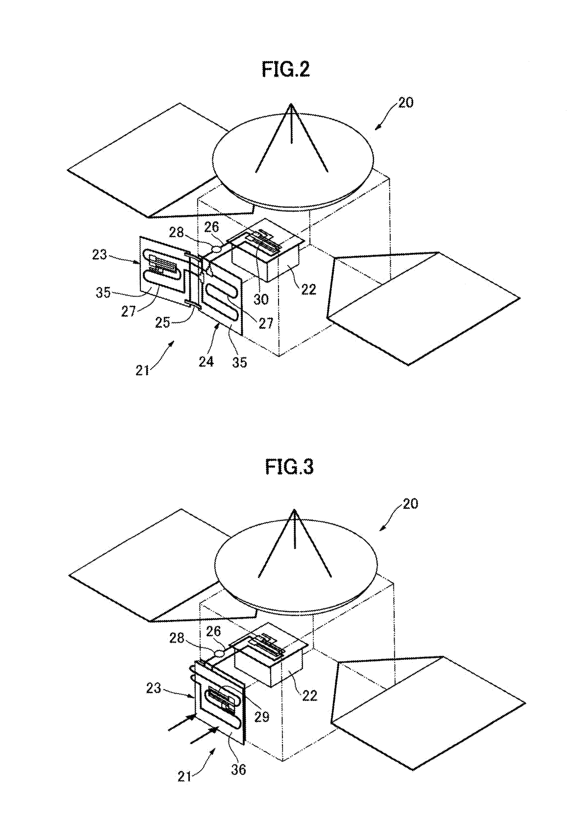
[0045]As a second embodiment of the present invention, a thermal control apparatus 21 for a medium or large spacecraft, which employs a fluid loop, will be described with reference to FIGS. 2 and 3. FIGS. 2 and 3 show a medium or large spacecraft 20 equipped with the thermal control apparatus 21 according to the second embodiment, wherein a heat-exchange paddle 23 of the thermal control apparatus 21 illustrated in FIG. 2 is set in its opened (i.e., deployed) position, and the heat-exchange paddle 23 illustrated in FIG. 3 is set in its closed (i.e., retracted) position.

[0046]The thermal control apparatus 21 comprises a heat-receiving member 22 which encloses or covers an on-board device generating heat, the heat-exchange paddle 23, a base plate 24, a deploying / retracting mechanism 25 and a fluid loop 26. The heat-exchange paddle 23 and the base plate 24 have a pipe 27 attached onto respective surfaces thereof to extend all over the surfaces while allowing fluid to flow therethrough. ...

third embodiment

[0050]As a third embodiment of the present invention, a thermal control apparatus 41 for a medium or large spacecraft, which employs a combination of a fluid loop and a high-temperature-heat transport element, will be described with reference to FIGS. 4 and 5. FIGS. 4 and 5 show a medium or large spacecraft 40 equipped with the thermal control apparatus 41 according to the third embodiment, wherein a heat-exchange paddle 43 of the thermal control apparatus 41 illustrated in FIG. 4 is set in its opened (i.e., deployed) position, and the heat-exchange paddle 43 illustrated in FIG. 5 is set in its closed (i.e., retracted) position.

[0051]The thermal control apparatus 41 comprises a heat-receiving member 42 which encloses or covers an on-board device generating heat, the heat-exchange paddle 43, a base plate 44, a deploying / retracting mechanism 45 and a fluid loop 46. The base plate 44 has a pipe 47 attached onto a surface thereof to extend all over the surface while allowing fluid to fl...


PUM


Abstract

Disclosed is a thermal control apparatus which comprises a base plate associated with a target object in a heat-exchangeable manner therebetween, at least one heat-exchange paddle attached to the base plate in such a manner as to be selectively deployed and retracted, paddle drive means provided at an end of the base plate and adapted to drive a deployment movement and a retraction movement of the heat-exchange paddle so as to change an angle of the heat-exchange paddle, and a heat transport element provided to connect the base plate and the heat-exchange paddle.

Description

CROSS-REFERENCE TO RELATED APPLICATIONS[0001]The present patent application claims priority from Japanese Patent Application No. 2007-111144, filed on Apr. 20, 2007.BACKGROUND OF THE INVENTION[0002]1. Field of the Invention[0003]The present invention relates to a thermal control apparatus suitable for use in cosmic environments or ground environments with large temperature changes, to thermally control a device, such as an on-board device for spacecrafts.[0004]2. Description of the Related Art[0005]In spacecrafts to be exposed to both low-temperature and high-temperature environments, it is necessary to keep an on-board device within an allowable temperature range. Typically, a thermal design for the on-board device is performed in conformity to high temperature environments, and a temperature-keeping control based on heating with a heater is combined therewith in low-temperature environments. However, in spacecrafts to be exposed to large environmental changes, such as moon / planeta...

Claims


Application Information

Patent Timeline
IPC IPC(8): B60H1/00
CPCB64G1/506F28F13/00F28F2013/005
Inventor OHNISHI, AKIRANAGANO, HOSEI
Owner JAPAN AEROSPACE EXPLORATION AGENCY
Why Eureka
Try Eureka