Method of and device for cooling blown film during the production of blown film

a technology of blown film and cooling film, which is applied in the field of cooling blown film during the production of blown film, can solve the problems of important access to the annular nozzle, adverse effects of the upper cooling ring,

Active Publication Date: 2008-10-23
K DESIGN CO LTD
View PDF12 Cites 28 Cited by
  • Summary
  • Abstract
  • Description
  • Claims
  • Application Information

AI Technical Summary

Benefits of technology

[0015]In accordance with the above-mentioned processes, an embodiment of a device according to the invention can be provided wherein at least a first annular cooling gas nozzle is directed against the extraction direction of the blown film and wherein at least a further annular cooling gas nozzle is directed in the extraction direction of the blown film. In addition, circumferentially variably controllers can be provided in sectors for controlling the volume flow. In addition, or in the alternative, the circumferentially variably controllers can be provided in sectors for controlling the temperature of the cooling gas flow of at least one of the annular cooling gas nozzles. In addition, or in the alternative, at least two annular cooling gas nozzles can be provided and directed in the extraction direction of the blown film. In addition, or in the alternative, at least two annular cooling gas nozzles can be provided and directed opposed to the extraction direction of the blown film. In addition, or in the alternative, at least two annular cooling gas nozzles can be provided and directed opposed to the extraction direction of the blown film. In order to avoid disadvantageous effects of the emissions emitted by the blown film after having left the annular nozzle, it is proposed that, between the annular nozzle of the film blowing head and the first annular cooling gas nozzle directed against the extraction direction of the blown film, a gas removal or a sucking-off device can be provided for cooling gas, which gas removal device can be provided to extend and / or be distributed around the circumference. The gas removal device can be comprised of individual gas-removal elements attached to hoses, as a result of which mounting and dismantling procedures can be simplified. To protect the film blowing head from cooling down, which is preferably kept at a constant temperature, an annular thermal insulator or an annular deflection plate can be provided above the film blowing head.
[0016]In an embodiment of the invention, at least one annular cooling gas nozzle can be provided and directed against the extraction direction of the blown film and the at least one annular cooling gas nozzle can be directed in the extraction direction of the blown film. These nozzles can comprise a common cooling ring or cooling ring module. In an embodiment of the invention, one common annular chamber can be provided to be supplied with cooling gas via circumferentially distributed connecting sleeves, and prior to the cooling gas finally leaving the cooling ring module, the cooling gas can be divided into individual cooling gas flows.
[0017]According to an alternative embodiment, at least one annular cooling gas nozzle can be directed against the extraction direction of the blown film and can constitute an element of a first cooling ring or cooling ring module. The at least one annular cooling gas nozzle can be directed in the extraction direction of the blown film and can constitute an element of a second cooling ring or cooling ring module. These two modules, too, can be supplied by one single cooling gas blower, with the cooling gas flow being divided in front of the cooling ring modules. However, it is also possible to provide a dedicated blower for each cooling ring module for ensuring a separate cooling gas supply. Providing two cooling ring modules is advantageous in that the distance between them can be varied, so that in addition to controlling the cooling gas quantity, the length of the cooling path can be varied too, if desired. The two cooling ring modules can be supplied with respective adjusting devices. Between the first cooling ring module and the second cooling ring module a further cooling ring in form of a disc-shaped housing can be arranged.
[0018]Further design details will be explained below with reference to the drawings.

Problems solved by technology

In this case, the effect of the upper cooling ring can be adversely affected in that the cooling gas emerging from the lower cooling ring has already been heated along the blown film and enters the upper cooling ring from below.
Furthermore, access to the annular nozzle, which is important when starting the system, can be complicated by the lower cooling ring positioned on the film blowing head.

Method used


Image

  • Method of and device for cooling blown film during the production of blown film
  • Method of and device for cooling blown film during the production of blown film
  • Method of and device for cooling blown film during the production of blown film

Examples


Embodiment Construction

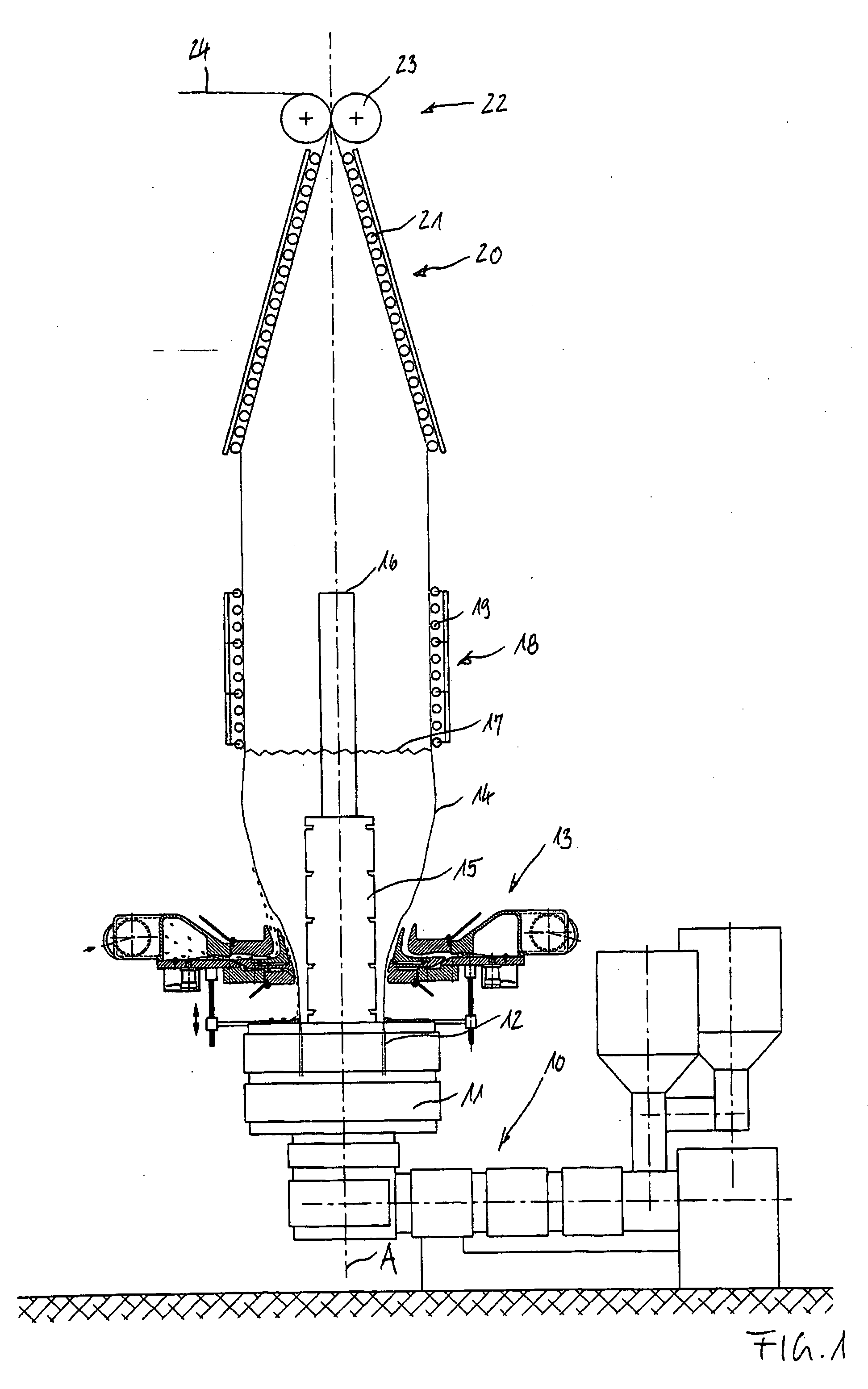
[0032]The device shown in FIG. 1 comprises a blown film extruder 10 with a film blowing head 11 which forms an annular nozzle 12 for producing a blown film 14. The joint axis A of the film blowing head 11, of the annular nozzle 12 and of the blown film 14 can be provided to extend vertically. The extraction direction of the blown film can extend from the bottom to the top.

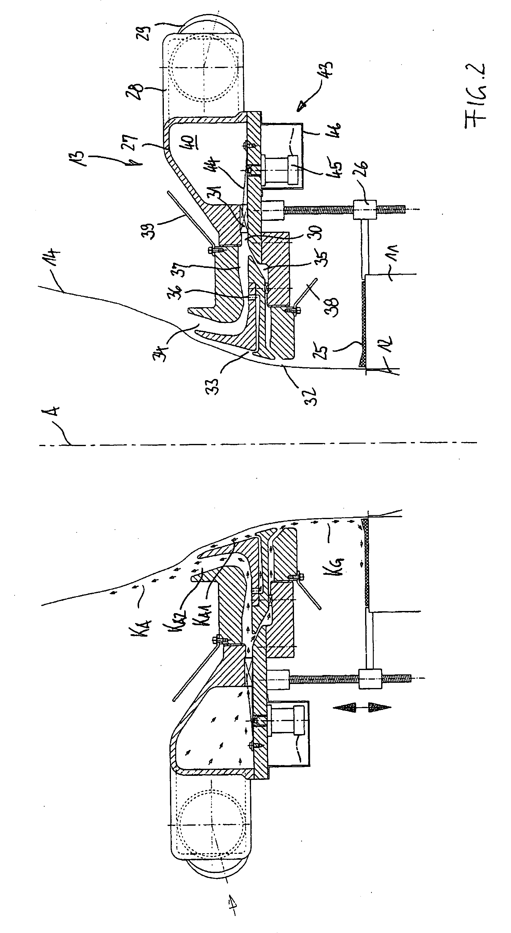
[0033]Above, and at a distance from the film blowing head 11, a co-axially arranged cooling ring 13 can be provided which can emit cooling gas for cooling the blown film 14 and whose details of the embodiment shown here will be explained in connection with FIG. 2. Inside the blown film 14 an inner cooling device 15 is provided with a gas removal device, i.e., an inner suction device 16 for further cooling gas. The cooling ring 13 can comprise one or more annular cooling gas nozzles which can generate via a venturi effect a widening effect on the blown film 14 so that the diameter of the latter can be increased in a...


PUM

PropertyMeasurementUnit
distanceaaaaaaaaaa
temperatureaaaaaaaaaa
circumferenceaaaaaaaaaa

Abstract

A method of cooling blown film consisting of thermoplastic plastics during the production of blown film by means of a blown film extruder with a film blowing head which comprises an annular nozzle from which the blown film emerges and is guided away in an extraction direction, wherein at least two cooling gas flows are made to approach the blown film from the outside in at least two blowing-out planes located at a distance from the annular nozzle, wherein at least one cooling gas flow KG is blown out in the direction opposed to the extraction direction of the blown film and wherein at least one cooling gas flow KA is blown out in the extraction direction of the blown film, and wherein, at least one of the cooling gas flows KG, KA can be controlled around their circumference in sectors, at least in respect of its volume flow or temperature.

Description

BACKGROUND AND SUMMARY OF THE INVENTION[0001]The invention relates to a method of cooling blown film comprising thermoplastic plastics during the production of blown film by means of a blown film extruder with a film blowing head which comprises an annular nozzle from which the blown film emerges and is guided away in an extraction direction. At least two cooling gas flows are made to approach the blown film from the outside in at least two blowing-out planes located at a distance from the annular nozzle. The invention also relates to a device for cooling blown film comprising of thermoplastic plastics during the production of blown film arranged at a blown film extruder with a film blowing head comprising an annular nozzle from which the blown film emerges and is guided away in an extraction direction. At least two annular cooling gas nozzles are arranged at a distance from the annular nozzle from at least two blowing-out planes for cooling gas.[0002]The blown film can be produced ...

Claims


Application Information

Patent Timeline
Patent Type & Authority Applications(United States)
IPC IPC(8): B29C47/88B29C48/10B29C48/76B29C48/90B29C48/92
CPCB29C47/0026B29C47/0057B29C47/0059B29C47/883B29C47/8835B29C47/903B29L2023/001B29C2947/92152B29C2947/92428B29C2947/926B29C2947/92647B29C2947/92704B29C2947/92923B29C47/92B29C48/906B29C48/908B29C48/913B29C48/10B29C48/92B29C48/903B29C48/9125B29C48/0018B29C48/0019B29C2948/926B29C2948/92152B29C2948/92428B29C2948/92647B29C2948/92704B29C2948/92923
Inventor ZIMMERMANN, RICHARD
Owner K DESIGN CO LTD
Why Eureka
Try Eureka