Multiple Location Load Control System

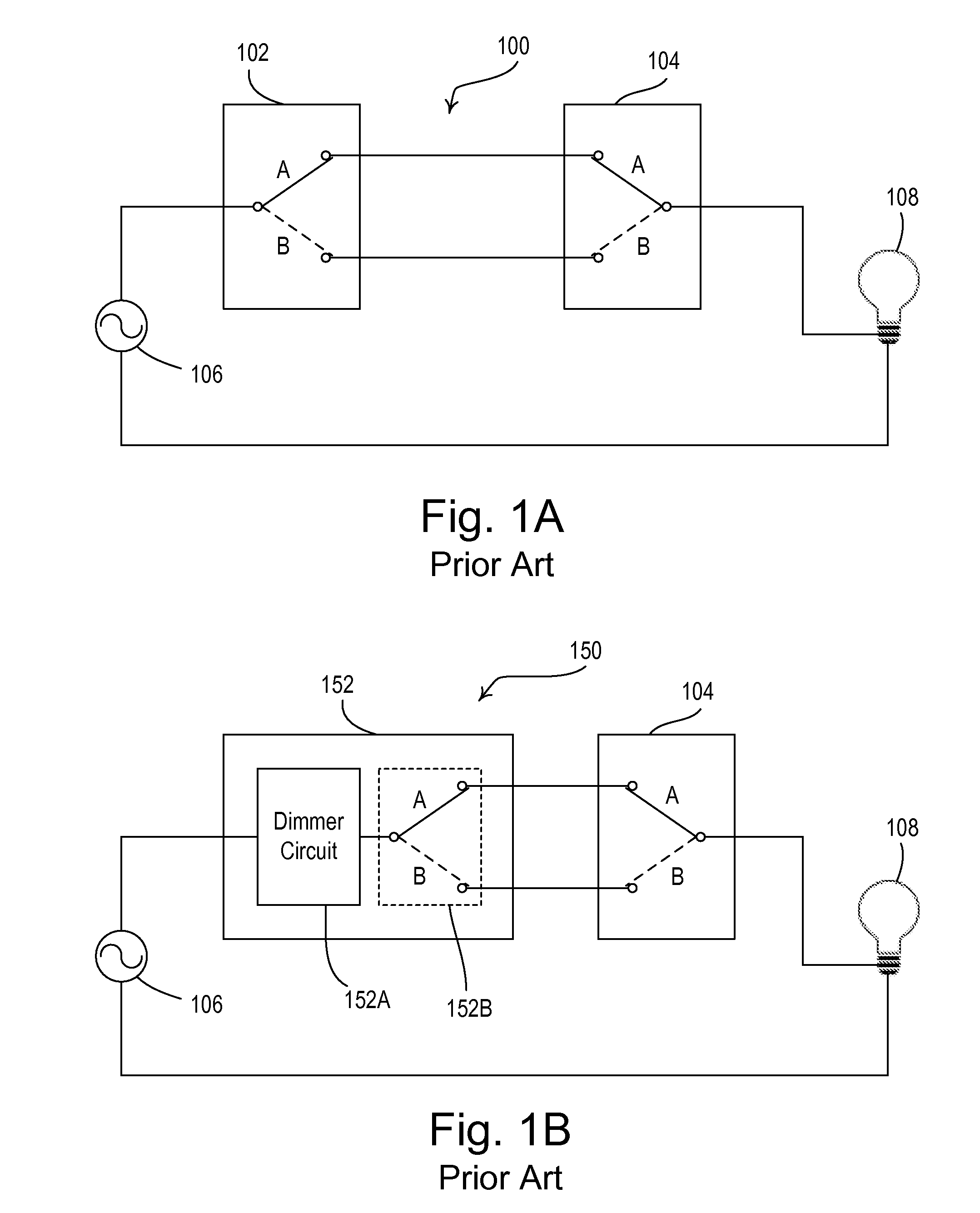
a load control system and multiple location technology, applied in the direction of electric variable regulation, process and machine control, instruments, etc., can solve the problem that the dimmer switch 152 is not able to provide the advanced set of features of a smart dimmer to the end user

Active Publication Date: 2008-10-23
LUTRON TECH CO LLC
View PDF30 Cites 91 Cited by
  • Summary
  • Abstract
  • Description
  • Claims
  • Application Information

AI Technical Summary

Benefits of technology

[0029]According to an embodiment of the present invention, a multiple location load control system for controlling an amount of power delivered to an electrical load from an AC power source comprises a main load control device and a remote load control device. The main load control device is adapted to be coupled in series electrical connection between the AC power source and the electrical load for control of the amount of power delivered to the electrical load, and is operable to conduct a load current from the AC power source to the electrical load. The remote load control device is adapted to be coupled in series electrical connection with comprising a power supply, the main load control device and the remote load control device adapted to be coupled in series electrical connection between the AC power source and the electrical load, and is also and operable to conduct athe load current from the AC power source to the electrical load. The remote load control device comprises a power supply and is adapted to be further coupled to the main load control device through an accessory wiring. The main load control device is operable to enable a charging path to allow the power supply of the remote load control device to charge through the accessory wiring during a first time period of a half-cycle of the AC power source. The main load control device and the remote load control device are operable to communicate with each other via the accessory wiring during a second time period of the half-cycle.

Problems solved by technology

Thus, the dimmer switch 152 is not able to provide the advanced set of features of a smart dimmer to the end user.

Method used


Image

  • Multiple Location Load Control System
  • Multiple Location Load Control System
  • Multiple Location Load Control System

Examples


first embodiment

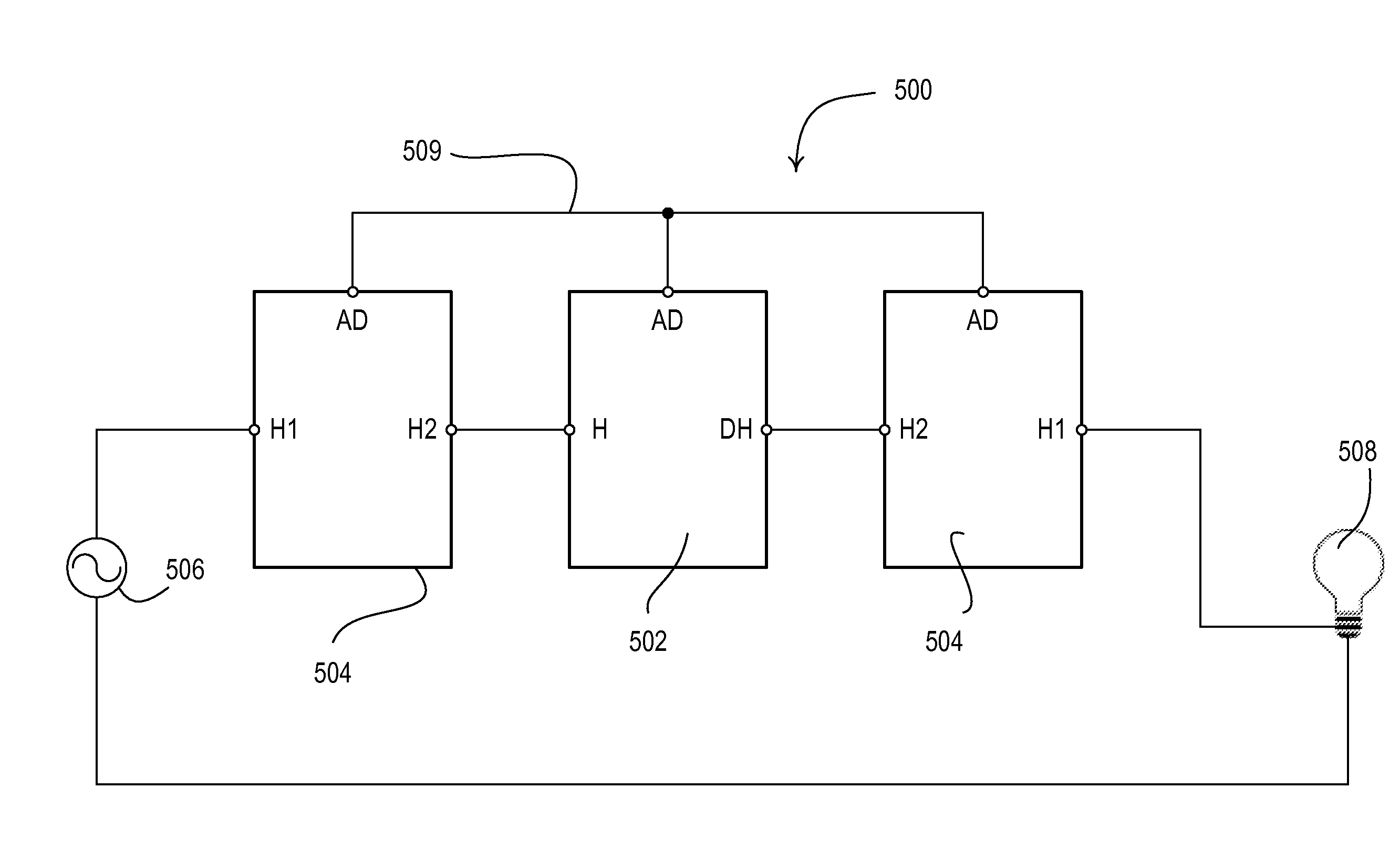
[0070]FIG. 5 is a simplified block diagram of a multiple location dimming system 500 according to the present invention. As shown in FIG. 5, a main dimmer 502 and two remote dimmers 504 (i.e., accessory dimmers) are coupled in series electrical connection between an AC power source 506 and a lighting load 508. The main dimmer 502 includes a hot terminal H (i.e., a line-side load terminal) adapted to be coupled to the line-side of the system 500 and a dimmed-hot terminal DH (i.e., a load-side terminal) adapted to be coupled to the load-side of the system 500. The main dimmer further comprises a load control circuit coupled between the hot and dimmed-hot terminals for controlling the amount of power delivered to the lighting load 508 (as will described in greater detail with reference to FIG. 7). The remote dimmers 504 include two hot terminals H1, H2, which conduct the load current from the AC power source 506 to the lighting load 508. The main dimmer 502 and the remote dimmers 504 e...

second embodiment

[0136]FIG. 23 is a simplified block diagram of a main dimmer 2302 according to the present invention. The bidirectional semiconductor switch of the main dimmer 2302 comprises first and second FETs 2310, 2311 coupled in anti-series connection for control of the amount of power delivered to the lighting load 508. The FETs 2310, 2311 are controlled by a controller 2314 via first and second gate drive circuits 2312, 2313, respectively. Specifically, the controller 2314 is operable to control the FETs 2310, 2311 using the reverse phase control dimming technique, such that the FETs are rendered conductive at the beginning of each half-cycle and then rendered non-conductive a specific time each half-cycle to control the amount of power delivered to the lighting load 508. The FETs 2310, 2311 may be, for example, part number FDPF2710T, manufactured by Fairchild Semiconductors. A current sense resistor R2317 is coupled between the FETs 2310, 2311 and generates a sense voltage having a magnitu...

third embodiment

[0149]FIG. 25 is a simplified block diagram of a multiple location dimming system 2500 having a main dimmer 2502 and two remote dimmers 504 according to the present invention. According to the second embodiment, the main dimmer 2502 must be located on either the load-side of the system 2500 (i.e., directly to the lighting load 508 as shown in FIG. 25) or the line-side of the system (i.e., directly to the AC power source 506).

[0150]FIG. 26 is a simplified block diagram of the main dimmer 2500 and the remote dimmer 504 according to the third embodiment of the present invention. The main dimmer 2500 comprises a single switching circuit 2636 coupled between the dimmed hot terminal DH and the accessory dimmer terminal AD, such that the switching circuit 2636 provides a charging path for the power supply 730 of the remote dimmer 504. A controller 2614 controls the switching circuit 2636 to be conductive to allow the power supply 730 of the remote dimmer 504 to charge during a charging tim...


PUM


Abstract

A multiple location load control system comprises a main device and remote devices, which do not require neutral connections, but allow for visual and audible feedback at the main device and the remote devices. The main device and the remote devices are adapted to be coupled in series electrical connection between an AC power source and an electrical load, and to be further coupled together via an accessory wiring. The remote devices can be wired on the line side and the load side of the load control system, such that the main device is wired “in the middle” of the load control system. The main device is operable to enable a charging path to allow the remote devices to charge power supplies through the accessory wiring during a first time period of a half-cycle of the AC power source. The main device and the remote devices are operable to communicate with each other via the accessory wiring during a second time period of the half-cycle.

Description

RELATED APPLICATIONS[0001]This application claims priority from commonly-assigned U.S. Provisional Application Ser. No. 60 / 925,782, filed Apr. 23, 2007, and U.S. Provisional Application Ser. No. 61 / 016,027, filed Dec. 21, 2007, both entitled MULTIPLE LOCATION LOAD CONTROL SYSTEM. The entire disclosures of both applications are hereby incorporated by reference.BACKGROUND OF THE INVENTION[0002]1. Field of the Invention[0003]The present invention relates to multiple location load control systems having multiple smart load control devices, and more particularly, a multiple location dimming system that includes a smart dimmer and one or more remote dimmers for controlling the amount of power delivered to a lighting load, where all of the smart dimmers and the remote dimmers are operable to display a present intensity level of the lighting load on a visual indicator.[0004]2. Description of the Related Art[0005]Three-way and four-way switch systems for use in controlling electrical loads, ...

Claims


Application Information

Patent Timeline
Patent Type & Authority Applications(United States)
IPC IPC(8): H05B39/04
CPCH05B37/0254H05B37/0263H05B37/02H05B39/044H05B39/041H05B47/185H05B47/18Y02B20/00H05B47/165H05B47/175
Inventor STEINER, JAMES P.BABY, CYRILBUCK, CHRISTOPHERCARMEN, DANIEL F.
Owner LUTRON TECH CO LLC
Why Eureka
Try Eureka