Pedestal Apparatus and Satellite Tracking Antenna Having the Same

a technology of satellite tracking and pedestal, which is applied in the direction of building scaffolds, machine supports, other domestic objects, etc., can solve the problems of high manufacturing cost, difficult stabilization control, and inconvenient use of conventional pedestal apparatuses, so as to reduce the size of radome, facilitate maintenance, and reduce the manufacturing cost

Inactive Publication Date: 2008-10-23
ELECTRONICS & TELECOMM RES INST
View PDF6 Cites 35 Cited by
  • Summary
  • Abstract
  • Description
  • Claims
  • Application Information

AI Technical Summary

Benefits of technology

[0009]A pedestal apparatus and a satellite tracking antenna having the same in accordance with the present invention have following advantages.
[0010]The three-axis pedestal apparatus according to the present invention can stabilize the tracking antenna mounted at a moving object although the moving object is yawing, rolling and pitching.
[0011]By disposing a vibration attenuating unit between a radome and a pole connected to the moving object, the size of the radome is minimized, a manufacturing cost thereof is reduced and easy maintenance is allowed.
[0012]Furthermore, by disposing a driving unit at a sensor cage for an additional rotating axis, the sensor cage is enabled to constantly maintain a horizontal level although the target direction of the satellite tracking antenna is changed.

Problems solved by technology

However, the conventional pedestal apparatuses are not suitable for a moving object having a wide moving range.
Also, it is not easy to control for stabilizing the attitude of a satellite tracking antenna, and it requests a high manufacturing cost.

Method used


Image

  • Pedestal Apparatus and Satellite Tracking Antenna Having the Same
  • Pedestal Apparatus and Satellite Tracking Antenna Having the Same
  • Pedestal Apparatus and Satellite Tracking Antenna Having the Same

Examples


Embodiment Construction

[0019]Other objects and aspects of the invention will become apparent from the following description of the embodiments with reference to the accompanying drawings, which is set forth hereinafter.

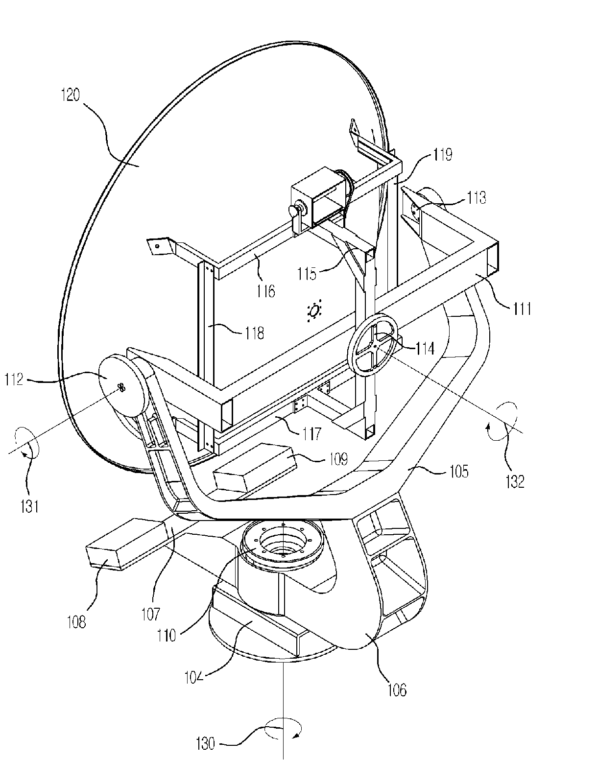
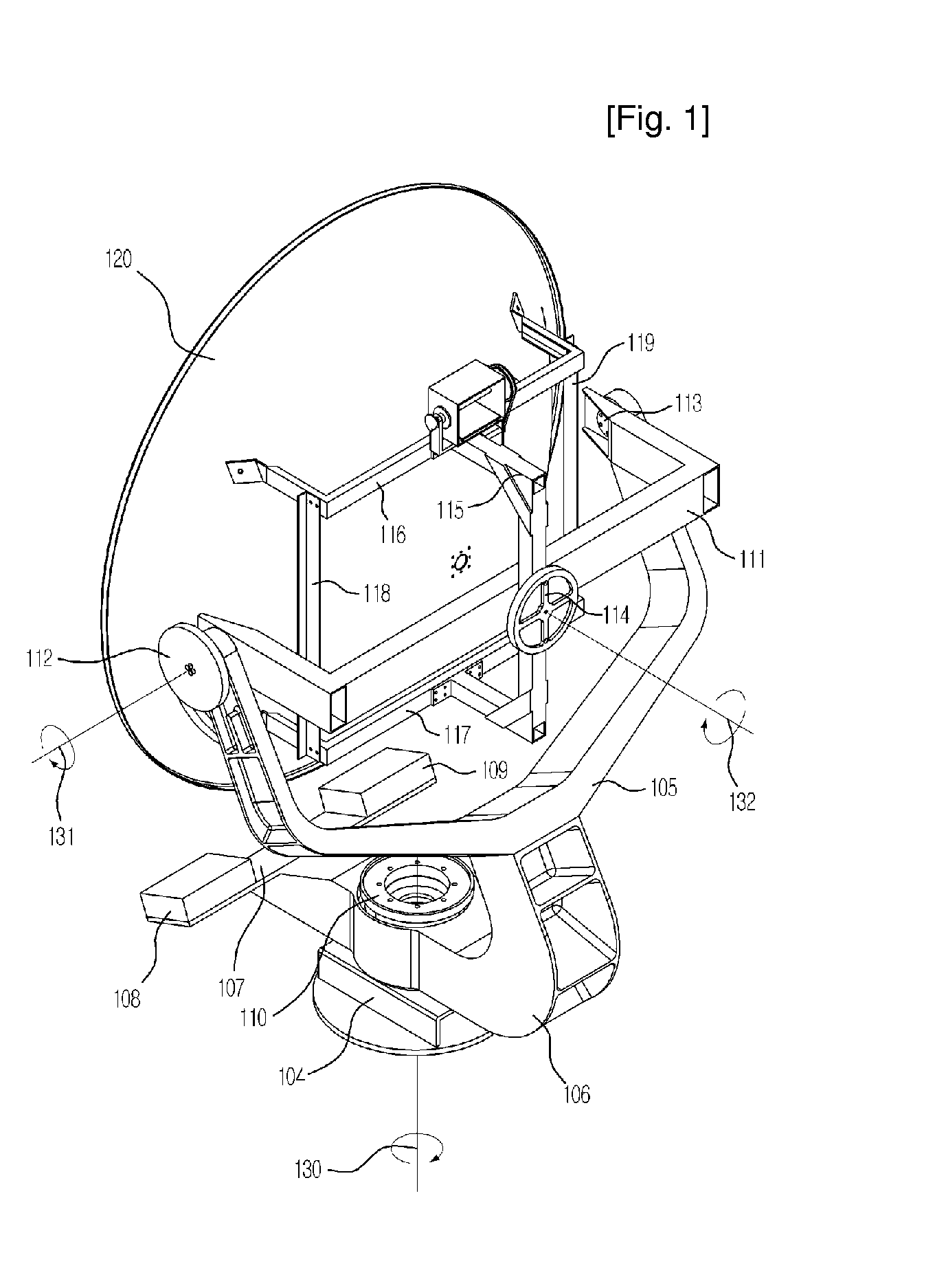
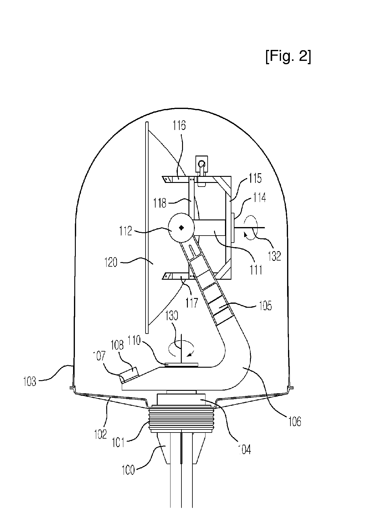
[0020]FIGS. 1 to 5 are views illustrating a satellite antenna having a pedestal apparatus in accordance with an embodiment of the present invention. FIG. 1 is a perspective view of a tracking antenna having a pedestal apparatus in accordance with an embodiment of the present invention. FIG. 2 is a side view of the tracking antenna of FIG. 1, and FIG. 3 is a rear view of the tracking antenna shown in FIG. 1. FIG. 4 is a front view of the tracking antenna shown in FIG. 1, and FIG. 5 is a perspective view illustrating a sensor cage mounted at the tracking antenna of FIG. 1.

[0021]As shown in FIG. 1, the pedestal apparatus according to the present embodiment includes a fixing unit 104, a first connecting unit 110, a first rotation supporting unit having a Y-shaped top supporting member 105 and a...


PUM


Abstract

Provided are a pedestal apparatus and a satellite-tracking antenna having the same. The pedestal apparatus includes: a fixing unit fixed at a moving object; a connecter for forming a first rotating axis vertically to the fixing unit; a first rotation supporter having a bottom fixed at the fixing unit and a Y-shaped top for rotating the tracking antenna around the first rotating axis; a second connecter connected to ends of the Y-shaped top for forming a second rotating axis; a second rotation supporter having both ends connected to the both ends of the second connecter for rotating the tracking antenna around the second rotating axis; a third connecter for forming a third rotating axis at a center of the second rotation supporter; and a supporter connected to the third connecter in a predetermined shape for supporting the tracking antenna, wherein the first, second and third rotating axes are not crossed one another.

Description

TECHNICAL FIELD[0001]The present invention relates to a pedestal apparatus for stabilizing the attitude of a tracking antenna mounted at a moving object and a satellite antenna having the same; and, more particularly, to a pedestal apparatus having three axes for sustaining the attitude of the satellite antenna mounted at a moving object to face a target satellite although the moving object such as a ship is yawing, rolling or pitching.BACKGROUND ART[0002]An antenna is mounted at a moving object to receive and transmit a signal from and to a satellite. The antenna mounted at the moving object is controlled to track a target satellite while the moving object is moving. Since the antenna is vibrated by the motion of the moving object, the motion of the moving object is compensated to accurately control the antenna.[0003]As conventional technology for compensating the motion of the moving object, a stabilized antenna system was introduced in U.S. Pat. No. 5,359,337. The conventional st...

Claims


Application Information

Patent Timeline
Patent Type & Authority Applications(United States)
IPC IPC(8): H01Q3/02
CPCH01Q1/125H01Q3/08H01Q19/10H01Q1/18H01Q15/16H01Q1/27
Inventor SON, SEONG-HOYUN, JAE-SEUNGJUNG, YOUNG-BAEEOM, SOON-YOUNGJEON, SOON-IK
Owner ELECTRONICS & TELECOMM RES INST
Why Eureka
Try Eureka