Wire-assisted write device with high thermal reliability

a write device and wire-assisted technology, applied in the field of magnetic devices, can solve the problems of poor thermal reliability, rapid failure of the device, and substantial heat generation

Inactive Publication Date: 2008-10-23
SEAGATE TECH LLC
View PDF37 Cites 16 Cited by
  • Summary
  • Abstract
  • Description
  • Claims
  • Application Information

AI Technical Summary

Problems solved by technology

However, the small geometry of the conductor, combined with the high current through the conductor, results in substantial heat generation due to Joule heating.
Unless this heat ...

Method used


Image

  • Wire-assisted write device with high thermal reliability
  • Wire-assisted write device with high thermal reliability
  • Wire-assisted write device with high thermal reliability

Examples


Embodiment Construction

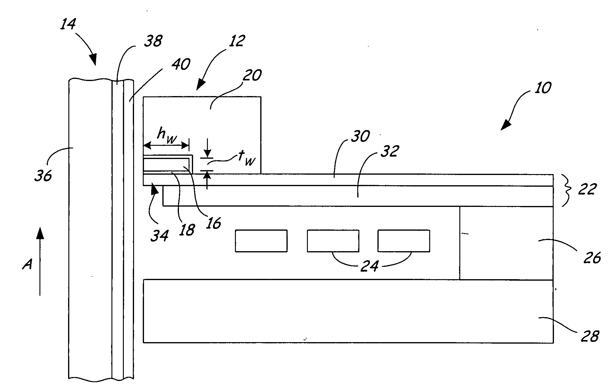
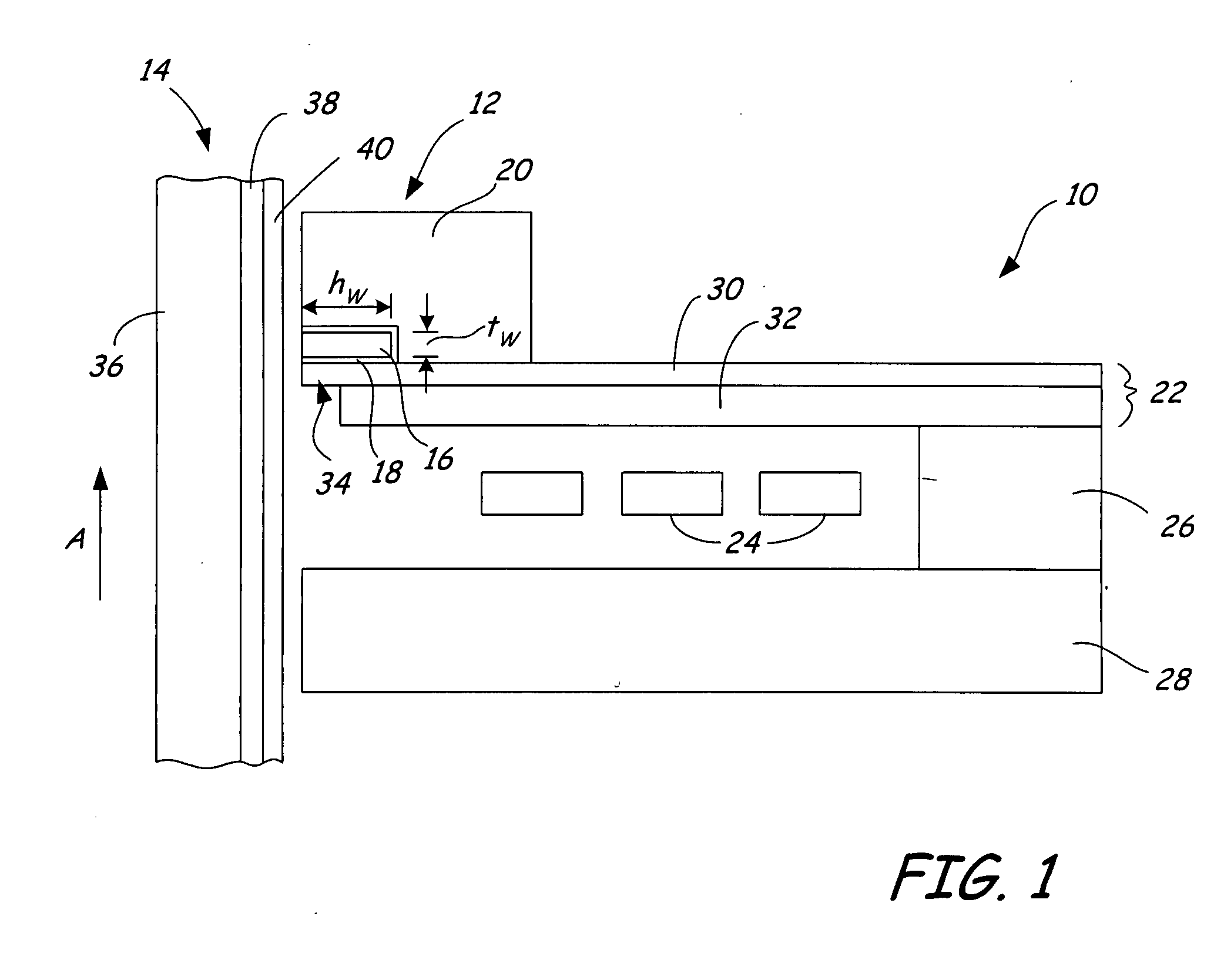
[0011]FIG. 1 is a side view of magnetic writer 10 and thermally reliable write assist element 12 disposed proximate to magnetic medium 14. Write assist element 12 includes conductor 16 having height hw and thickness tw, insulating material 18, and heat sink 20. Magnetic writer 10 includes write pole 22, conductive coils 24, back via 26, and return pole 28. Write pole 22, which includes main portion 30 and yoke portion 32, is connected to return pole 28 by back via 26 distal from the front surface of magnetic writer 10 that confronts magnetic medium 14. Conductive coils 24 surround back via 26 such that turns of conductive coils 24 are disposed in the gap between write pole 22 and return pole 28.

[0012]Magnetic writer 10 is carried over the surface of magnetic medium 14, which is moved relative to magnetic writer 10 as indicated by arrow A such that write pole 22 is the trailing pole and is used to physically write data to magnetic medium 14. Conductive coils 24 surround back via 26 s...


PUM


Abstract

A magnetic device includes a first pole having a first pole tip. A conductor, which is adjacent to an edge of the first pole tip, carries current to generate a second field that augments a first field generated by the first pole. The width of the conductor is in the range of about one to about five times the width of the trailing edge of the first pole tip.

Description

BACKGROUND OF THE INVENTION[0001]The present invention relates to magnetic devices. More particularly, the present invention relates to a magnetic device that employs a current-carrying conductor to provide a magnetic field that augments a write field.[0002]Two general techniques for magnetically recording information on a storage medium include longitudinal recording and perpendicular recording. In longitudinal recording, the direction of the magnetic field in a plane of the storage medium is altered in a manner to store information. In perpendicular recording, the magnetic field is impressed into the storage medium in a direction that is perpendicular to the plane of the medium. With the magnetic field direction perpendicular to the plane of the medium as opposed to parallel with the plane, information can be stored at higher density.[0003]There has been an ongoing effort to increase the bit densities in magnetic recording. Bit density refers to the number of flux reversals (i.e.,...

Claims


Application Information

Patent Timeline
IPC IPC(8): G11B5/23G11B5/127
CPCG11B5/1278G11B5/3116G11B5/3143G11B2005/0005
Inventor KIEF, MARK T.VAN EK, JOHANNESLINVILLE, ERIC S.VAVRA, WILLIAM P.VAS'KO, VLADYSLAV A.
Owner SEAGATE TECH LLC
Why Eureka
Try Eureka