
Communication Node and Communication Control Method

a communication control and communication node technology, applied in the field of communication node and communication control method, can solve the problems of delay and packet loss, multi-homing controller cannot recognize, and the address the multi-homing controller has selected as a source address no longer accurately indicates the current location of the mn,

Active Publication Date: 2008-10-23
REDWOOD TECHNOLOGIES LLC
View PDF4 Cites 28 Cited by
  • Summary
  • Abstract
  • Description
  • Claims
  • Application Information

AI Technical Summary

Benefits of technology

[0162]While taking the above described problems into account, the present invention provides the effects that, when the communication node includes both a mobility management function and a multihoming function, an appropriate address can be selected from multiple addresses in a multihomed state.

Problems solved by technology

However, since the multihoming controller is so designed that it is not concerned with the moving of the communication node, and only manages a plurality of addresses maintained by the communication node, the multihoming controller does not recognize that the address managed by the multihoming controller is an HoA or a CoA for the mobile IP, since the communication node has moved.
Further, in a case wherein a CoA obtained at a connection destination is allocated for the interface, the address the multihoming controller has selected as a source address no longer accurately indicates the current location of the MN.
Thus, a packet is transmitted using an inappropriate address that has been selected, and there are problems in that various defects, such as delays and packet losses, may occur.
Likewise, in this case, as shown in FIG. 30, wherein a multihoming controller is located lower than a mobile IP, appropriate cooperation for address selection is not available between an MIP controller and the multihoming controller, and a resulting problem is that a condition (an address selection condition) due to the multihomed state of an MN is not appropriately reflected.
Therefore, according to the prior art, the problem is that, even in a case wherein MN1.CoA2 should be designated as a source address for a packet, in accordance with an address selection condition that is due to multihoming, only an address limited to the ULID that is selected by the MIP controller 2020 is designated as a source address for a packet.

Method used


Image

  • Communication Node and Communication Control Method
  • Communication Node and Communication Control Method
  • Communication Node and Communication Control Method

Examples


first embodiment

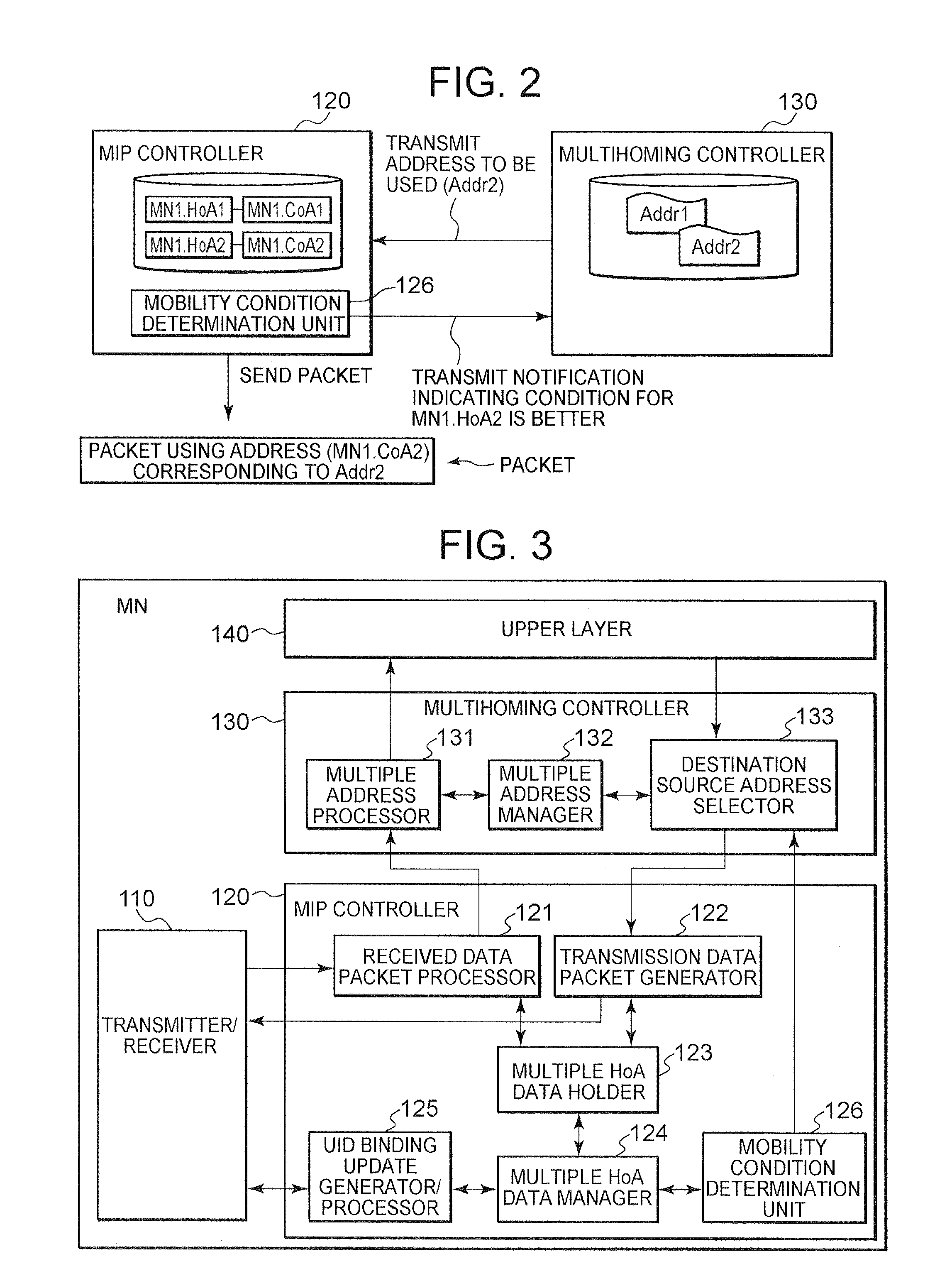
[0205]The first embodiment of the present invention will now be described. FIG. 2 is a schematic diagram showing the internal arrangement of an MN to explain the overview of the first embodiment of the invention.

[0206]An MIP controller 120 and a multihoming controller 130 mounted in an MN are shown in FIG. 2. It should be noted that the presence of the MIP controller 120 indicates that a protocol, such as an MIP that achieves mobility management, is mounted in the MN, and the presence of the multihoming controller 130 indicates that a protocol that achieves multihoming is mounted in the MN.

[0207]The MIP controller 120 according to the first embodiment of the invention includes a mobility condition determination unit 126. The mobility condition determination unit 126 includes a function that obtains and examines various conditions (hereinafter called mobility conditions) that occur as the MN moves, and that, based on this mobility condition, determines the most appropriate set of an ...

second embodiment

[0283]Next, the second embodiment of the present invention will be described. FIG. 11 is a schematic diagram showing the internal arrangement of an MN to explain the overview of the second embodiment of the invention.

[0284]An MIP controller 220 and a multihoming controller 230 mounted in an MN are shown in FIG. 11. It should be noted that, as well as in FIG. 2, the presence of the MIP controller 220 indicates that a protocol, such as an MIP that achieves mobility management, is mounted in the MN, and the presence of the multihoming controller 230 indicates that a protocol that achieves multihoming is mounted in the MN.

[0285]The MIP controller 220 according to the second embodiment of the invention includes a mobility condition determination unit 226. The mobility condition determination unit 226 includes a function that obtains and examines a mobility condition, and based on this mobility condition, determines the most appropriate set of an HoA and a CoA for the current connection s...

third embodiment

[0298]Next, the third embodiment of the present invention will be described. FIG. 13 is a schematic diagram showing the internal arrangement of an MN to explain the overview of the third embodiment of the invention.

[0299]An MIP controller 320 and a multihoming controller 330 mounted in an MN are shown in FIG. 13. It should be noted that, as well as in FIG. 2, the presence of the MIP controller 320 indicates that a protocol, such as an MIP that achieves mobility management, is mounted in the MN, and the presence of the multihoming controller 330 indicates that a protocol that achieves multihoming is mounted in the MN.

[0300]The MIP controller 320 according to the third embodiment of the invention includes a mobility condition notification unit 327. The mobility condition notification unit 327 includes a function for transmitting, to the multihoming controller 330, a mobility condition available for the MIP controller 320.

[0301]Assume that, for example, the MN is in the multihomed stat...


PUM


Abstract

A technique is disclosed whereby, in the case of wherein a communication node includes both a mobility management function and a multihoming function, based on a condition that occurs due to moving, an appropriate address can be selected from multiple addresses in a multihomed state. According to the technique, a mobility condition determination unit 126, provided in an MIP controller 120 that manages moving of a communication node, obtains and examines various conditions that has occurred as a communication node is moving, selects an appropriate HoA (e.g., the home address of an MN1) for the current connection situation, and transmits, to a multihoming controller 130, a notification indicating that a set of the selected HoA and a CoA is appropriate addresses to be used. Upon receiving the notification from the mobility condition determination unit, the multihoming controller transmits, to the MIP controller, an address (Addr2) consonant with the received HoA, and the MIP controller performs packet communication using the HoA or the CoA consonant with the address.

Description

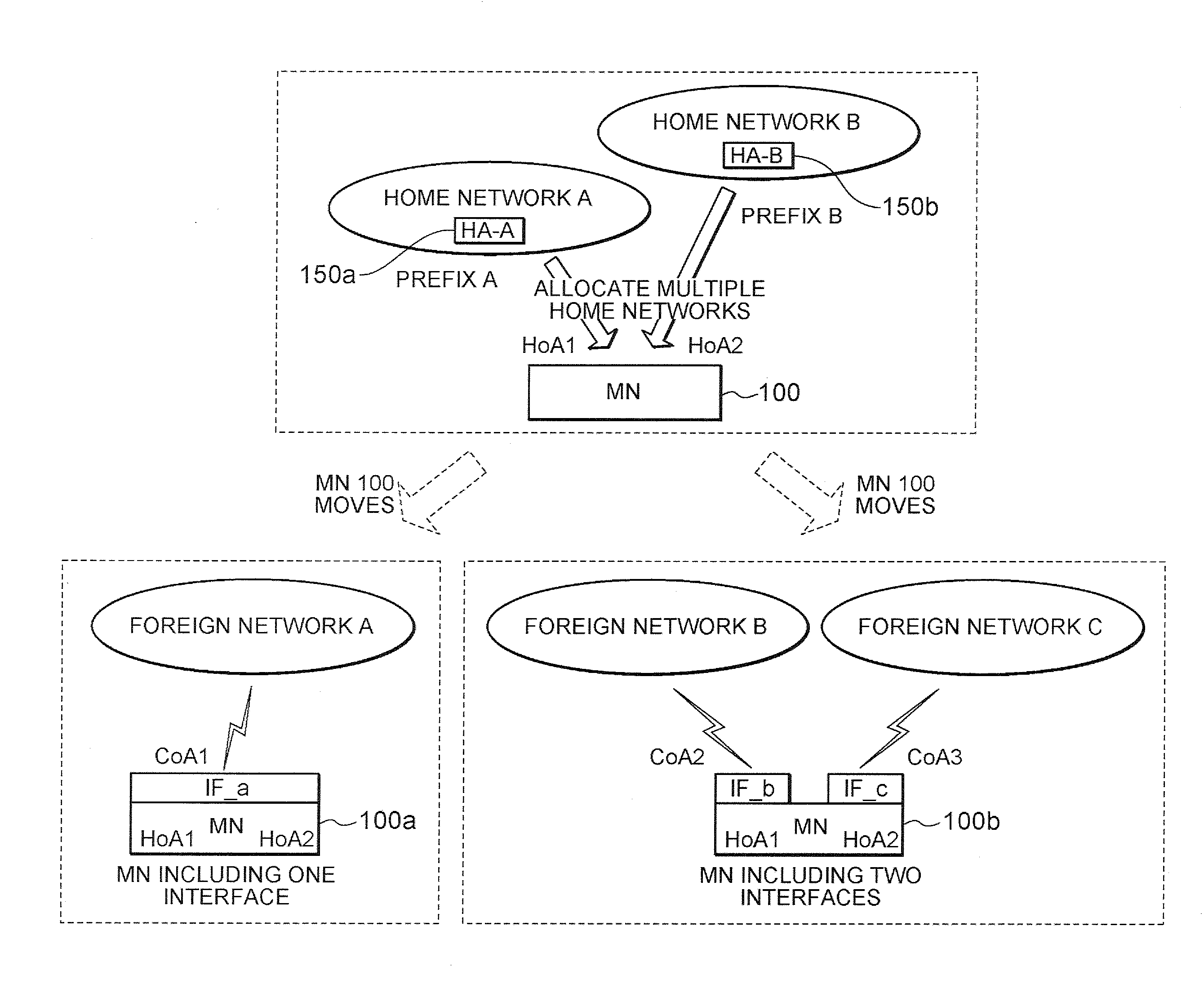
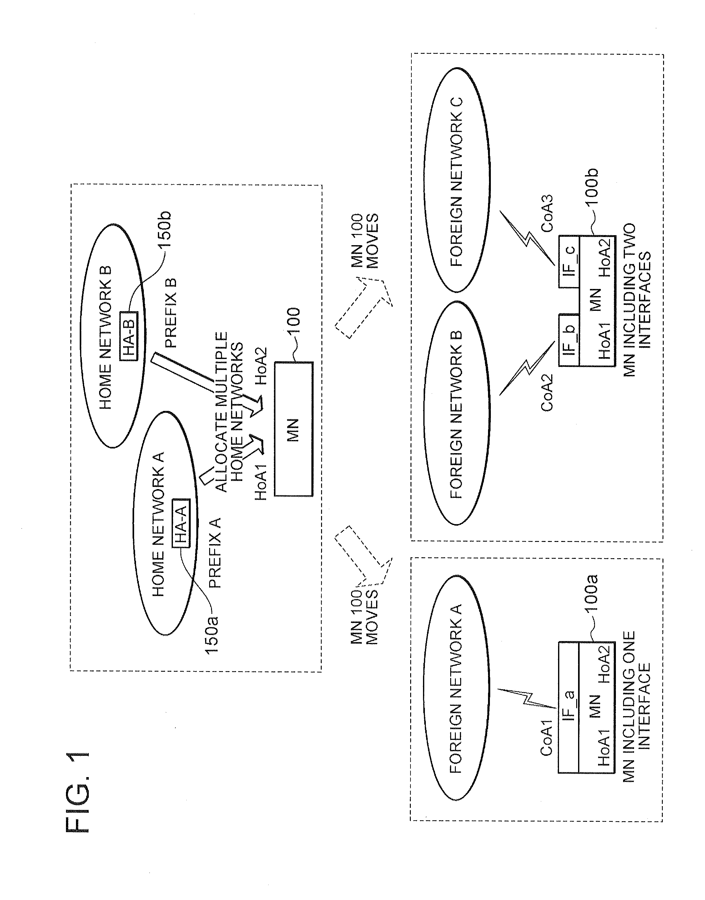
TECHNICAL FIELD[0001]The present invention relates to a communication node and a communication control method for performing communication using the IP (Internet Protocol), and particularly to a communication node in which both a multihoming function and a mobile function are mounted, and a communication control method therefor.BACKGROUND ART[0002]First, an explanation will be given for a case wherein a communication node is in a multihomed state. Furthermore, it is assumed that a multihomed state described herein indicates a state wherein a specific communication node maintains a plurality of IP addresses (hereinafter also referred to simply as addresses) configured based on different prefixes.[0003]There are, roughly, the two following cases wherein a communication node is in a multihomed state.[0004]First case: case wherein a network to which a communication node is connected is transmitting (advertising) a plurality of different prefixes.[0005]Second case: case wherein a communi...

Claims


Application Information

Patent Timeline
IPC IPC(8): H04Q7/00H04W8/10H04W80/04
CPCH04L29/12311H04L29/12952H04L61/2084H04L61/6077H04W8/10H04W80/04H04L61/5084H04L2101/677
Inventor ASO, KEIGOHIRANO, JUNKOH, TIEN-MING BENJAMINNG, CHAN WAHTAN, PEK YEW
Owner REDWOOD TECHNOLOGIES LLC
Learn More