Packet transfer rate monitoring control apparatus method and program

a technology of monitoring apparatus and transfer rate, applied in the field of packet transfer rate monitoring control apparatus, can solve the problem of not ensuring the minimum guaranteed rate of some flows

Inactive Publication Date: 2004-04-08
NEC CORP
View PDF7 Cites 83 Cited by
  • Summary
  • Abstract
  • Description
  • Claims
  • Application Information

AI Technical Summary

Benefits of technology

0010] It is the first object of the present invention to provide a packet transfer rate monitoring control apparatus and the like which, in a packet communication network in which the minimum guaranteed rate and maximum limiting rate of packet transfer are contracted for each service which a subscriber uses, can ensure a packet transfer rate higher than the minimum guaranteed rate even when traffic has increased.

Problems solved by technology

Unfortunately, these conventional packet transfer rate monitoring control apparatuses define a contracted value of the maximum limiting rate by several types of parameters, and, if this contracted value is violated, discard the packet or lower the priority of transfer by adding a tag indicating the contract violation to the packet header, so that the contracted value of the maximum limiting rate is not exceeded for all flows.
However, if these values are different and the total of the maximum limiting rates of individual flows is set to exceed the interface rate of the packet transfer apparatus, and if traffic increases temporarily, the minimum guaranteed rates of some flows are no longer ensured although each individual flow does not exceed the maximum limiting rate.

Method used


Image

  • Packet transfer rate monitoring control apparatus method and program
  • Packet transfer rate monitoring control apparatus method and program
  • Packet transfer rate monitoring control apparatus method and program

Examples


first embodiment

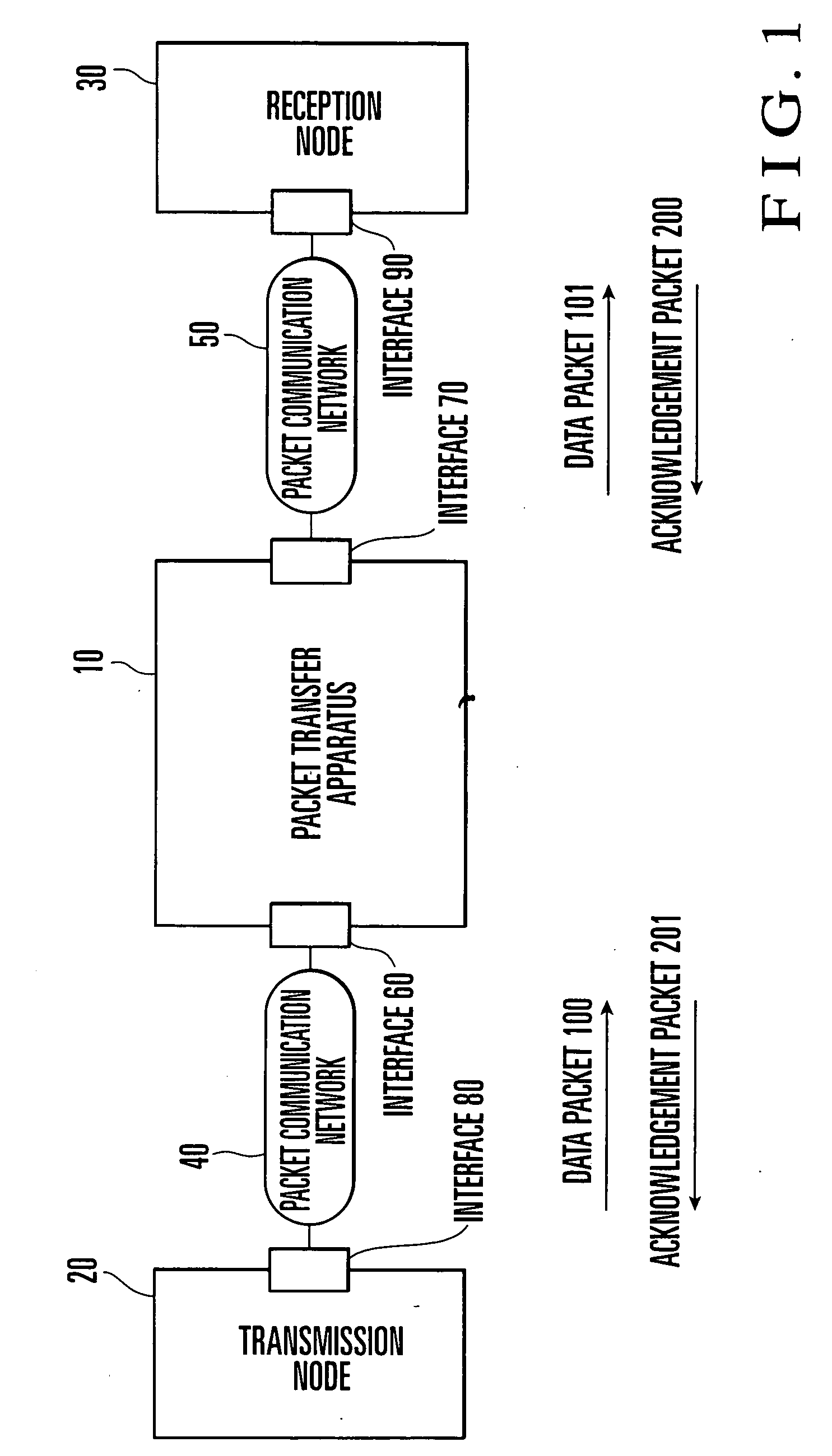
[0049] FIG. 1 is a block diagram showing an example of a packet communication network including a packet transfer apparatus to which the present invention is applied.

[0050] An outline of this packet communication network will be explained below.

[0051] A packet transfer apparatus 10 is connected to packet communication networks 40 and 50, respectively, via interfaces 60 and 70.

[0052] A transmission node 20 is connected to the packet communication network 40 via an interface 80. A reception node 30 is connected to the packet communication network 50 via an interface 90. The transmission node 20 outputs a data packet 100 to the reception node 30. The packet transfer apparatus 10 receives this data packet 100 from the interface 60.

[0053] The packet transfer apparatus 10 performs a routing process for the input data packet 100 on the basis of header information of the packet. After rewriting the packet's header information as needed, the packet transfer apparatus 10 outputs a data packet...

second embodiment

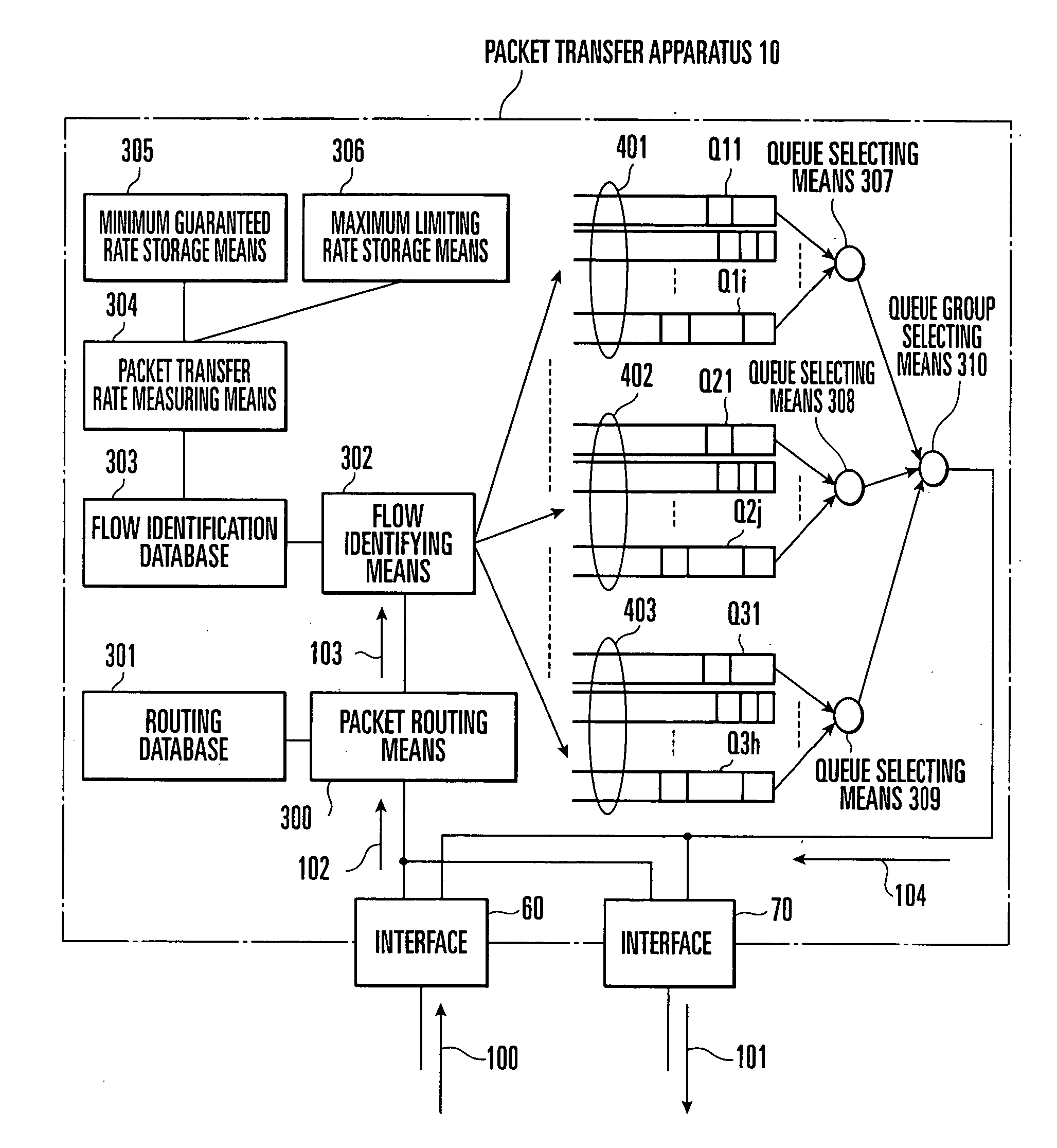
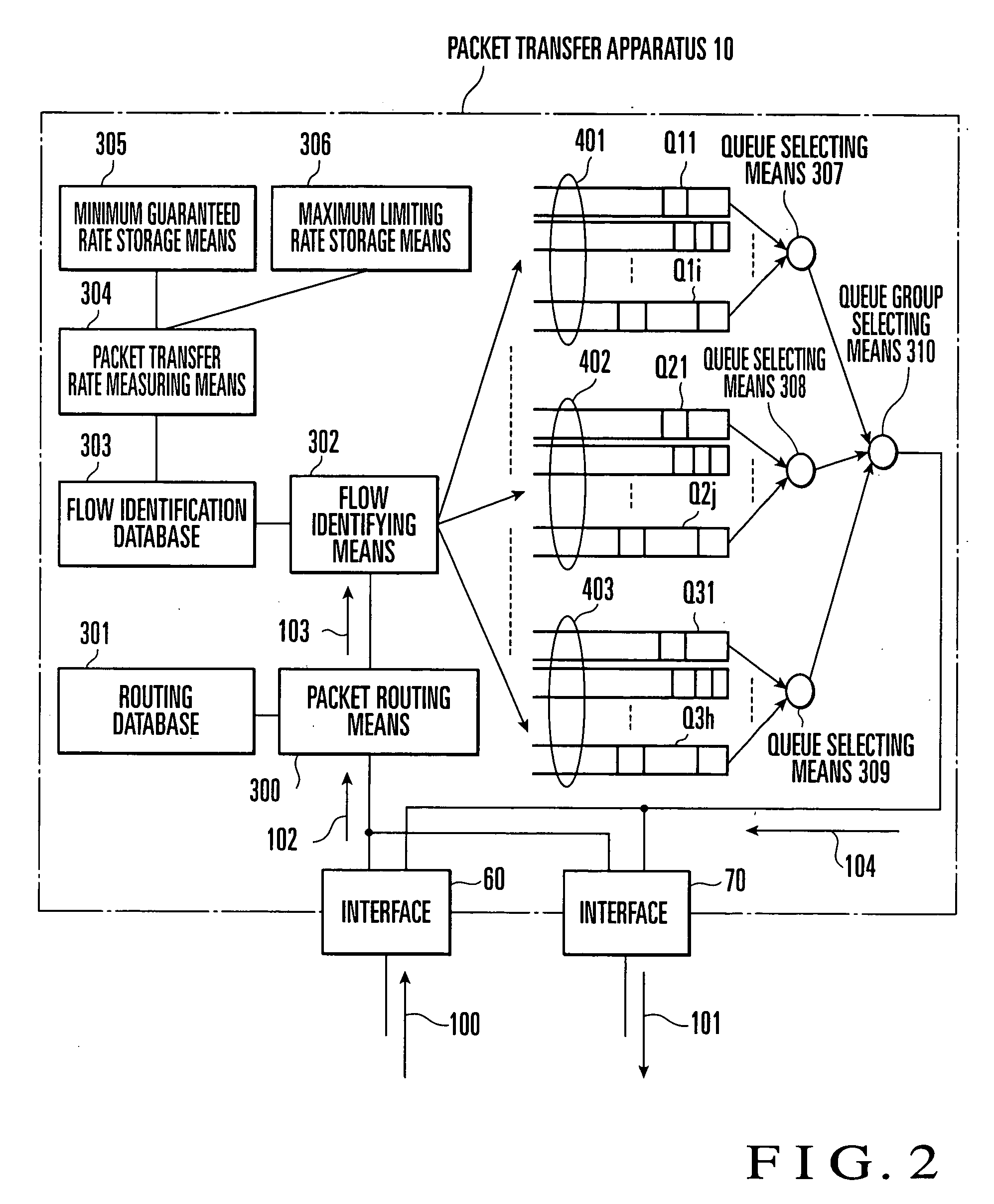
[0079] FIG. 4 is a block diagram showing the arrangement of a packet transfer apparatus 11 according to the present invention.

[0080] This packet transfer apparatus 11 includes interfaces 60 and 70, packet routing means 300, routing database 301, flow identifying means 302, flow identification database 303, packet transfer rate measuring means 311, minimum guaranteed rate storage means 312, maximum limiting rate storage means 313, queue selecting means 307a, 307b, 308a, 308b, and 309, and queue group selecting means 310.

[0081] In this second embodiment, groups of queues whose packet transfer rates are less than the minimum guaranteed rate are classified into 401a and 401b, and groups of queues whose packet transfer rates are equal to or higher than the minimum guaranteed rate and equal to or lower than the maximum limiting rate are classified into 402a and 402b. This classification is done as follows.

[0082] First, the packet transfer rate measuring means 311 holds a sum total Rsum of...

third embodiment

[0097] the present invention will be explained below.

[0098] The arrangement of a packet transfer apparatus according to this third embodiment is the same as the packet transfer apparatus 11 of the second embodiment described above.

[0099] A maximum limiting rate storage means 313 according to this third embodiment holds a total sum Msum of maximum limiting rates {M1, M2, . . . , Mi} preset for flows {F1, F2, . . . , Fi}, and a total sum Nsum of maximum flow rates {N1, N2, . . . , Ni} preset for flows {G1, G2, . . . , Gj}. This maximum limiting rate storage means 313 also calculates weighting coefficients {W1, W2, . . . , Wj} for the flows {F1, F2, . . . , Fi} by W1=M1 / Msum, W2=M2 / Msum, . . . , Wj=Mj / Msum, and weighting coefficients {V1, V2, . . . , Vj} for the flows {G1, G2, . . . , Gj} by V1=N1 / Nsum, V2=N2 / Nsum, . . . , Vj=Nj / Nsum, and holds these weighting coefficients.

[0100] Queues {Q11, Q12, . . . , Q1i} are classified into queue groups 401a and 401b on the basis of the weighting...


PUM


Abstract

In a packet communication network in which the minimum guaranteed rate and maximum limiting rate of packet transfer are contracted for each service, this invention classifies flows corresponding to received packets into group 1 to which a flow whose packet transfer rate is less than the minimum guaranteed rate belongs, group 2 to which a flow whose packet transfer rate is equal to or higher than the minimum guaranteed rate and less than the maximum limiting rate belongs, and group 3 to which a flow whose packet transfer rate exceeds the maximum limiting rate belongs. A packet received in relation to a flow which belongs to group 1 is preferentially transferred before a packet received in relation to a flow which belongs to group 2, and a packet received in relation to a flow which belongs to group 2 is preferentially transferred before a packet received in relation to a flow which belongs to group 3. This allows easy and fair redistribution of an extra band, while a packet transfer rate equal to or higher than the minimum guaranteed rate is ensured, even when traffic has increased.

Description

[0001] The present invention relates to a packet transfer rate monitoring control apparatus, method, and program to be incorporated into a packet transfer apparatus, in a packet communication network in which the minimum guaranteed rate or maximum limiting rate of packet transfer is contracted for each subscriber or service.[0002] In packet communication using a high-speed access network such as two-way CATV or ADSL (Asymmetric Digital Subscriber Loop), it is a general practice to contract one or both of the minimum guaranteed rate and maximum limiting rate of packet transfer between a subscriber and the carrier, and decide a connection fee in accordance with the contracted value.[0003] Although one contract is made for each subscriber in some cases, a plurality of contracts are sometimes made in accordance with services such as data, audio, and video services which a subscriber uses. Especially when a carrier applies different charging systems to different services, the minimum gua...

Claims


Application Information

Patent Timeline
Patent Type & Authority Applications(United States)
IPC IPC(8): H04N17/00H04L47/22H04L47/265H04L47/32H04L47/52H04L47/525H04L47/6275
CPCH04L47/10H04L47/2483H04L47/2441H04L47/20
Inventor MATSUNAGA, YASUHIKO
Owner NEC CORP
Why Eureka
Try Eureka