Method of printing a receiving material with hot melt ink and an inkjet printer suitable for applying such a method

a technology of hot melt ink and receiving material, which is applied in the direction of printing, measurement devices, instruments, etc., can solve the problems of inability to form a uniform nip, noticeable decline in transfer yield, and inability to print uniformly, so as to improve printing properties, reduce surface tension, and improve printing

Inactive Publication Date: 2005-06-14
OCE TECH
View PDF7 Cites 58 Cited by
  • Summary
  • Abstract
  • Description
  • Claims
  • Application Information

AI Technical Summary

Benefits of technology

[0008]The object of the present invention is to obviate the above disadvantages. To this end, a printing method has been developed which utilizes an intermediate element provided with an elastomeric surface having a hardness of less than 80 Shore A, e.g., a Shore A hardness of greater than 0 to less than 80, a thermal conductivity coefficient greater than 0.15 W / mK, an ink absorption of less than 10%, and a tanδ of less than 0.3. It has surprisingly been realised that an elastomer with a sufficiently low hardness can also result in a suitable method, i.e. a method in which the transfer yield is high and the adhesion to the receiving material is sufficiently strong, provided the thermal conductivity coefficient, the ink absorption and the tanδ satisfy the above relationships. It has been unexpectedly found that when an elastomer is used with the criteria of the present invention, despite the relatively low nip pressure which can be achieved therewith (typically 1-10 bar), a transfer yield of 100% can nevertheless be achieved with the ink adhering satisfactorily to the receiving material. The reason for this is not completely clear but it is perhaps the favorable result of the low nip pressure that the ink also adheres less strongly to the surface of the intermediate element, so that less forces are needed to be overcome to be able to transfer the ink. However, this on its own cannot explain the entire invention, because too low a thermal conductivity coefficient in turn results in a noticeable decline in the transfer yield. If the thermal conductivity is too low, ink drops often appear to split in the transfer nip (cohesive failure) so that the transfer is similar to a stamping process with an associated low transfer yield. In the case of a soft elastomer, too high an ink absorption also results in a noticeable decline in the transfer yield. The low yield cannot be explained by ink remaining in the elastomer, often a few percent maximum in the printing process, but here again appears to be dominated by an incomplete transfer, i.e. ink drops which do not transfer or which only partially transfer. Finally, in the case of a soft elastomer, the tanδ of the elastomer appears to be significant. If this value is increased above the limit of the present invention, the transfer yield noticeably declines. The reason for this is not clear but it is possibly associated with the fact that such an elastomer will undergo permanent deformation more easily.
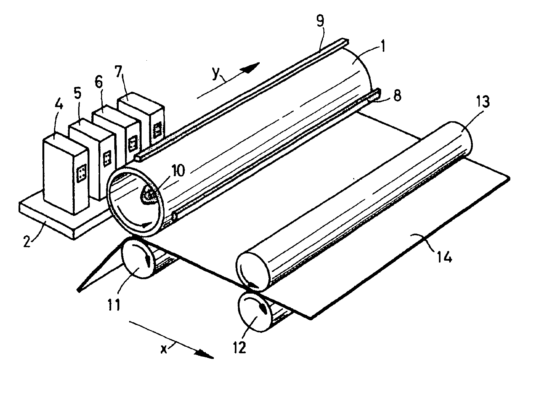
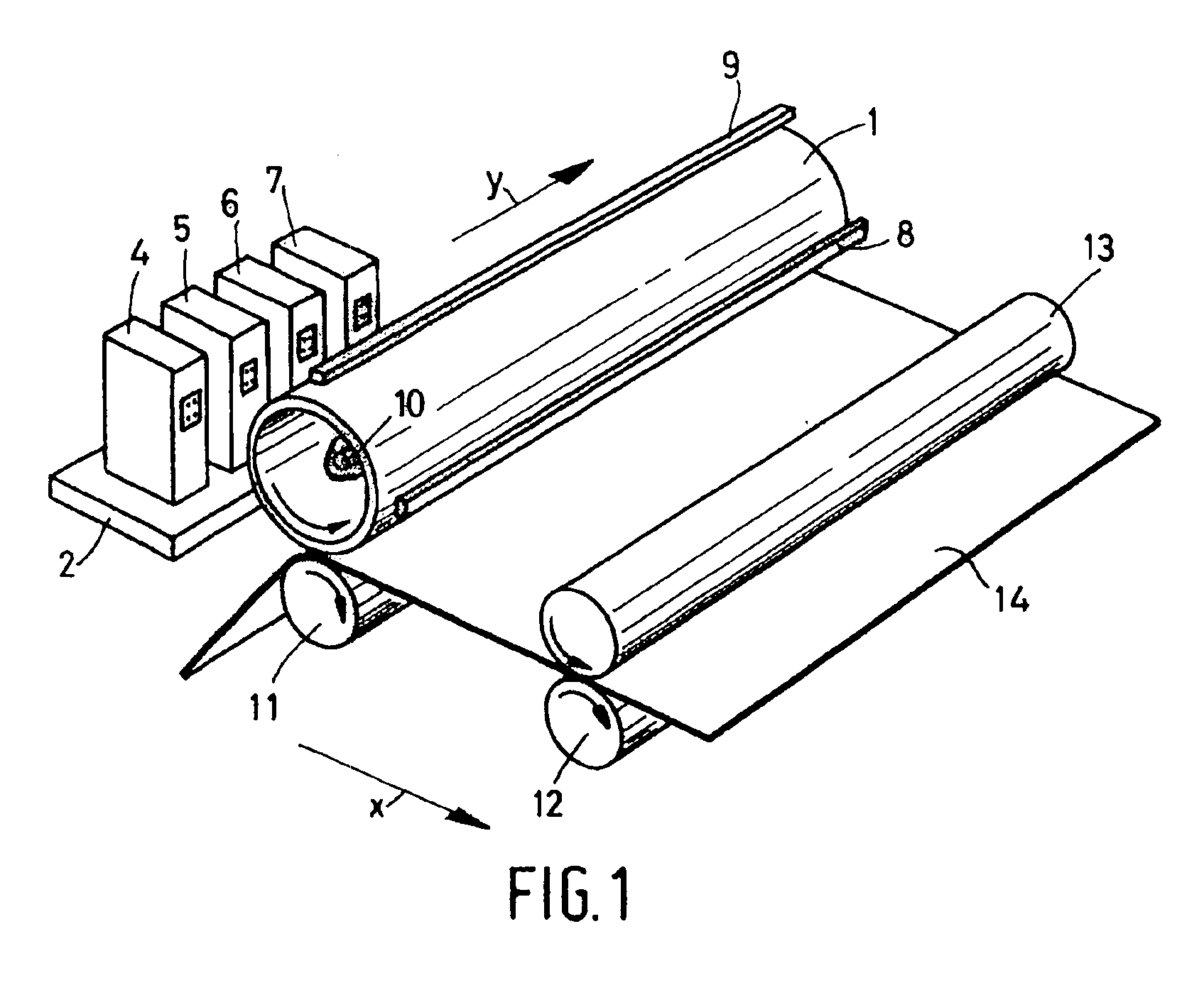
[0009]One of the advantageous features of the present invention is that it is possible to dispense with a rigid and hard intermediate element because it is no longer necessary to generate high pressures in the transfer nip. Abandoning high pressures means that it is possible to use a simple mechanical suspension for the intermediate element. Since the latter is no longer subjected to such high pressures, it is possible to use a much wider intermediate element, for example up to widths equal to those of the current large-format receiving materials (A3, A2 etc). At the same time, the intermediate element can be made much lighter, for example in the form of a relatively weak drum with a layer of elastomer thereon. This layer of elastomer also has the advantage that the momentum of a receiving sheet entering the transfer nip will be transmitted to a lesser degree over the periphery of the intermediate element, because the momentum can to a not inconsiderable extent be taken in the elastomer around the nip. An additional advantage of the use of an elastomer as a surface for the intermediate element is that the transfer nip can be formed by two intermediate elements between which the receiving material is fed. This makes it possible, in principle, for both surfaces of the receiving material to be printed simultaneously, resulting in high productivity. This is impossible in the known method because the hardness of the surface of each of the intermediate elements would make it impossible to form a uniform nip when two such elements together form the transfer nip.
[0010]The present invention also makes it possible to construct the intermediate element in the form of a belt. This has the advantage that a more compact print engine can be made because a belt can easily be trained around rollers in order to obtain a compact belt run. In addition, in the case of an intermediate element constructed as a belt, for example a perfluoropolyether rubber applied to a film, the impact of a sheet of receiving material in the transfer nip can be taken better because of the high deformability of the intermediate element over its entire length. Another advantage of a belt is that the exit angle at which the sheet of receiving material leaves the transfer nip can readily be adapted, for example by running the intermediate element in the transfer nip over a roller of a different diameter. Such an adaptation may be necessary to improve the sheet separation, i.e. releasing the sheet of receiving material from the intermediate element and the pressure roller when the sheet leaves the transfer nip. Also, the invention is not restricted to transfer elements consisting entirely of an elastomer. It is also possible to provide just the top layer of the transfer element with a layer of elastomer as specified by the method of the present invention. The carrier of this top layer may be any arbitrary material, for example a rubber which is in turn applied to a solid support such as a film or a fabric, or a metal or plastic carrier etc. which may or may not be rubberised.
[0011]The present invention provides more freedom in the choice of inks. This is important because the ink already has to meet many requirements: it must be capable of processing in an inkjet printhead, it must be able to enter into sufficient interaction with the receiving material, it must harden sufficiently rapidly after cooling (so that a printed receiving material can be rapidly subjected to mechanical load, for example by using it as an input to another printer) and it must be durable so that printed images do not spoil in the course of time.
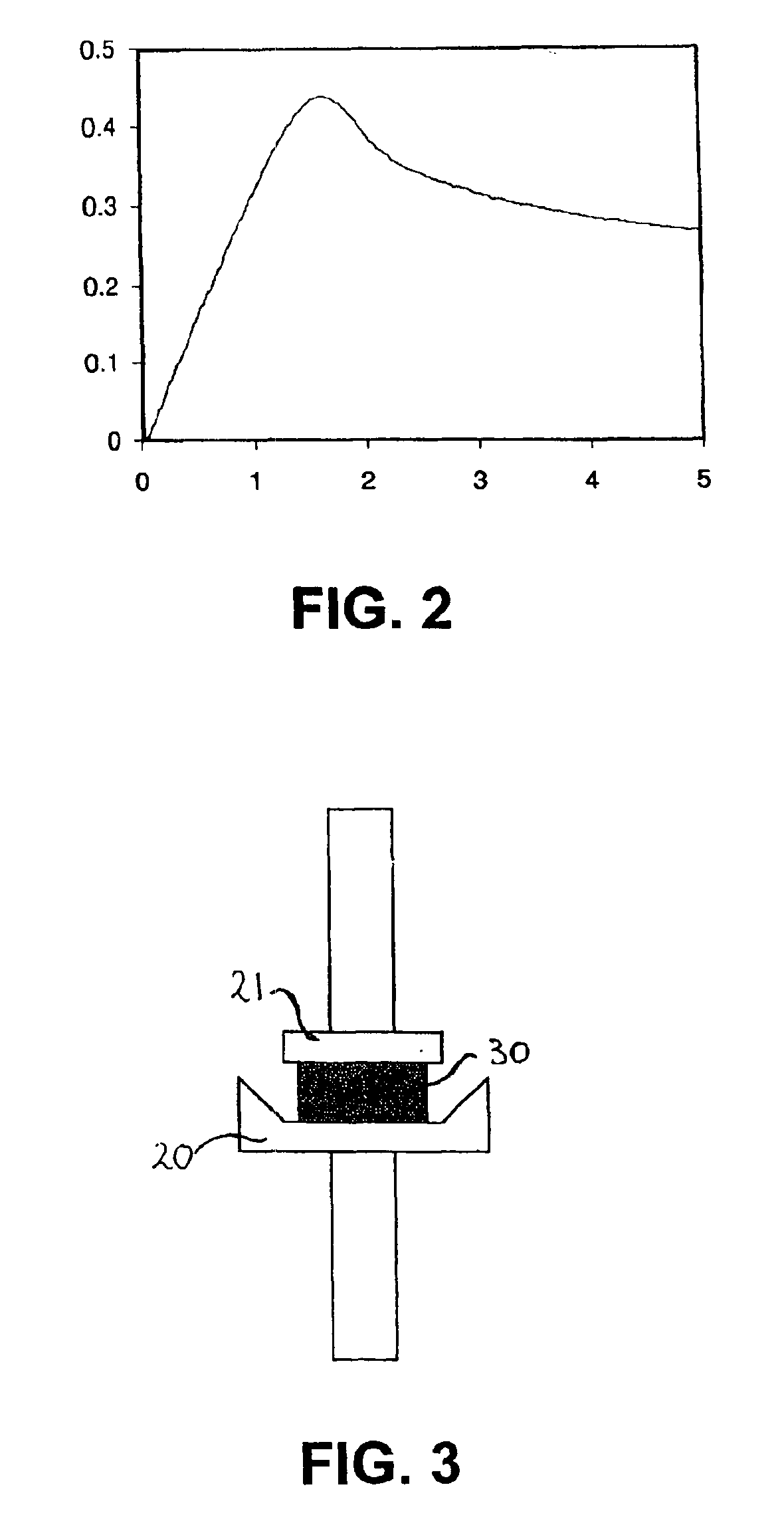
[0016]In a further embodiment of the present invention, the ink used has a deformation energy of less than 20×105 Pa.s at a top limit in the temperature at which the ink is pressure-transferable, e.g., greater than 0 to less than 20×105 Pa.s. It has been found that such inks in combination with the present method result in a printing process with a very good transfer yield of up to 100% and a good image quality. The present invention also relates to the combination of such an ink and a printer suitable for applying the present method. It has been surprisingly found that this combination results in very good print results despite the fact that the printer contains an intermediate element having a surface of a relatively soft elastomer.

Problems solved by technology

However, this on its own cannot explain the entire invention, because too low a thermal conductivity coefficient in turn results in a noticeable decline in the transfer yield.
If the thermal conductivity is too low, ink drops often appear to split in the transfer nip (cohesive failure) so that the transfer is similar to a stamping process with an associated low transfer yield.
In the case of a soft elastomer, too high an ink absorption also results in a noticeable decline in the transfer yield.
This is impossible in the known method because the hardness of the surface of each of the intermediate elements would make it impossible to form a uniform nip when two such elements together form the transfer nip.

Method used


Image

  • Method of printing a receiving material with hot melt ink and an inkjet printer suitable for applying such a method
  • Method of printing a receiving material with hot melt ink and an inkjet printer suitable for applying such a method
  • Method of printing a receiving material with hot melt ink and an inkjet printer suitable for applying such a method

Examples


example 2

[0029]The hardness in Shore A can be determined as described in ASTM Standard D 2240 of 1991.

example 3

[0030]Example 3 indicates how the thermal conductivity coefficient of an elastomer can be determined. The thermal conductivity is a measure of the heat flow through a material of a specific thickness as a result of a specific temperature difference over the material. This thermal conductivity can be measured using the Holometrix c-matic TCA 200. A sample of the material under investigation is made prior to the measurement. This sample is round with a diameter of 50 to 52 mm and has a thickness of between 6 and 12 mm. For a reliable measurement, the sample must have plain-parallelism such that there are no thickness differences of more than 0.1 mm. For an accurate determination of the thermal conductivity, the thickness of the sample must be known with an accuracy of 0.05 mm. For this purpose the thickness meter such as the Peacock model H can be used.

[0031]To obtain good contact between the sample and the two heat transmission plates of the TCA 200 the sample is provided with a thin...

example 4

[0033]This example indicates how the ink absorption of an elastomer can be determined. For this purpose, a sample of the elastomer for measurement is used with a thickness of about 2 mm and a surface area (in elevation) of 5.4 cm2. This sample is immersed in the relevant ink, which is maintained at 10° C. above its melting temperature. The relative increase in weight of the sample over time is determined by removing the sample from the ink at specific times, cleaning the surface and weighing the sample. As soon as there is no further weight increase (typically after 10-100 hours) the test is concluded. The final relative weight increase in percent is termed the ink absorption.

[0034]It has been found that elastomers usable in the method according to the present invention have an ink absorption lower than 10%. At higher ink absorption the transfer yield at the top limit (see Example 6 for the definition of the top limit) decreases noticeably and a relatively considerable amount of ink...


PUM


Abstract

A method of printing a receiving material with hot melt ink using an intermediate element having a surface containing an elastomer with a surface tension in which the polar part thereof is less than or equal to 20 mN / m, wherein the receiving material is brought into contact with the intermediate element in such manner that the ink transfers from the intermediate element to the receiving material, and wherein the elastomer has a hardness of less than 80 Shore A, a thermal conductivity coefficient greater than 0.15 W / mK, and in absorption of less than 10%, and a tanδ of less than 0.3.

Description

BACKGROUND OF THE INVENTION[0001]This non-provisional application claims priority under 35 U.S.C. § 119(a) on Patent Application No. 1021010 filed in The Netherlands on July Jul. 5, 2002, which is herein incorporated by reference.[0002]1. Field of the Invention[0003]The present invention relates to a method of printing a receiving material with hot melt ink which includes the steps of heating the ink to above a temperature at which it is liquid, imagewise transferring the liquid ink to an intermediate element using an inkjet printhead, the intermediate element having a surface containing an elastomer with a surface tension having a polar part equal to or less than 20 mN / m, and bringing the receiving material into contact with the intermediate element in such a manner that the ink transfers from the intermediate element to the receiving material. The present invention also relates to an inkjet printer suitable for applying the present method, the combination of such a printer with an...

Claims


Application Information

Patent Timeline
Patent Type & Authority Patents(United States)
IPC IPC(8): B41J2/005B41J2/01
CPCB41J2/0057B41J2/17593
Inventor KREMERS, MARTINUS ANTONIUSTHIJSSEN, MAURICE HENDRIKUS HUBERTINUSWEITENAUER, BERBY MARGA GERARDA
Owner OCE TECH
Why Eureka
Try Eureka