Landmark Navigation for Vehicles Using Blinking Optical Beacons

a technology of optical beacons and vehicles, applied in the field of positioning and navigation systems, can solve the problems of ins systems accruing errors as a function of time, unable to achieve precise navigation, and high cost of gps/ins positioning systems, and achieve accurate navigation. , to achieve the effect of auging other positioning systems

Active Publication Date: 2008-10-23
HARRIS CORP
View PDF10 Cites 87 Cited by
  • Summary
  • Abstract
  • Description
  • Claims
  • Application Information

AI Technical Summary

Problems solved by technology

When GPS capability is denied due to signal reception difficulties, then these devices turn to inertial navigation system (INS) techniques.
A GPS / INS positioning system is expensive and achieves precise navigation only when a significant view of the GPS satellites exists from time to time.
Furthermore, INS systems accrue error as a function of time because they use acceleration sensors to calculate position displacement through integration.
Therefore, every minute that a GPS / INS-based system does not see enough sky to cancel out the INS error, the position accuracy of the vehicle continues to worsen.
The sources of error with odometry are the uncertainty in the direction of motion at any instant and slippage of the vehicle's wheels on the terrain.
Thus, for applications that require very precise positioning determinations, it is not tolerable to have blackouts in the absolute positioning system.
The challenge in a landmark navigation system is in reliably identifying the landmarks in cluttered scenes.

Method used


Image

  • Landmark Navigation for Vehicles Using Blinking Optical Beacons
  • Landmark Navigation for Vehicles Using Blinking Optical Beacons
  • Landmark Navigation for Vehicles Using Blinking Optical Beacons

Examples


Embodiment Construction

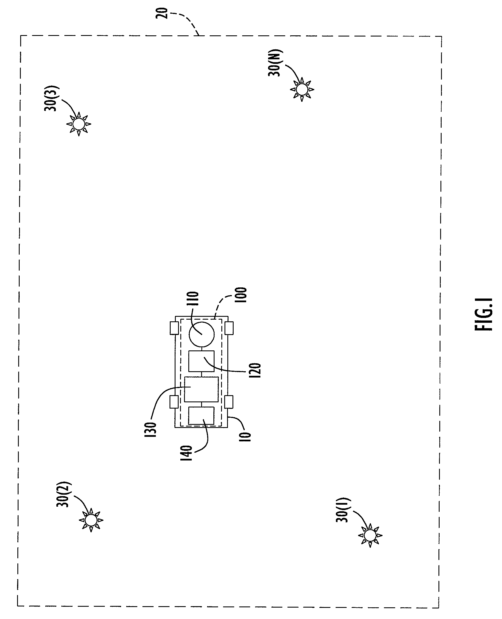
[0019]Referring first to FIG. 1, a vehicle is shown at reference numeral 10 that moves about within a field of operation shown at reference numeral 20. The vehicle may be a robotic self-controlled vehicle, or a remotely controlled vehicle, or any other vehicle on which it is desired to have navigation capabilities. The field of operation 20 may be a room inside a building, an entire building, an outdoor region such as a town or city, etc. Positioned throughout the field of operation 20 are optical beacons 30(1) to 30(N). In one embodiment, the positions or locations of the optical beacons 30(1) to 30(N) are known a priori or otherwise determined prior to deployment of a vehicle 20 in the field of operation. In another embodiment, the vehicle 20 determines the positions of the optical beacons by way of a self-surveying technique described hereinafter. The optical beacons may be positioned on the ceiling of a room or building or on a vertical structure (e.g., wall) for indoor applicat...


PUM


Abstract

A system and method for landmark navigation employing optical beacons deployed at locations throughout a field of operation of a vehicle. The optical beacons emit or reflect an optical signal at a predetermined blink frequency. The locations of the optical beacons may or may not be known to the vehicle. At least one imaging device on the vehicle, such as a digital camera, captures images in the field of operation, and in particular a pair of image frames such that the time interval between the image frames of the pair is equal to one-half of the blink period of the optical signal. Data is generated that represents a difference frame between two image frames captured by the imaging device. Pixel locations of optical beacons in the difference frame are identified. The position and orientation of the vehicle is determined from data representing pixel locations of optical beacons in the difference frame.

Description

BACKGROUND OF THE INVENTION[0001]The present invention is directed to positioning and navigation systems.[0002]Positioning and navigation systems are used in a wide range of applications. One particular application that presents unique challenges is in connection with robots or unmanned vehicles. Currently, a global positioning system (GPS) is virtually the only technique used for robot positioning in outdoor applications. Developments in this field have been made to accommodate the accuracy and limitations of GPS. When GPS capability is denied due to signal reception difficulties, then these devices turn to inertial navigation system (INS) techniques. A GPS / INS positioning system is expensive and achieves precise navigation only when a significant view of the GPS satellites exists from time to time. Moreover, it is still necessary to employ a source of differential GPS correction data from a radio transmitter station in communication with the vehicle. Furthermore, INS systems accru...

Claims


Application Information

Patent Timeline
Patent Type & Authority Applications(United States)
IPC IPC(8): G01C21/00
CPCG05D1/0246G05D1/0234G05D1/0244
Inventor FARWELL, MARK LALON
Owner HARRIS CORP
Why Eureka
Try Eureka