Hydraulic buoyancey kinetic energy apparatus

a kinetic energy apparatus and buoyance technology, applied in mechanical apparatus, engine components, machines/engines, etc., can solve the problems of kinetic energy or power not being completely stored, the quantity of generated electric power is reduced, and the power generator is useless without a power sour

Inactive Publication Date: 2008-10-30
TUNG JUI CHI
View PDF10 Cites 50 Cited by
  • Summary
  • Abstract
  • Description
  • Claims
  • Application Information

AI Technical Summary

Benefits of technology

[0007]The present invention will become more obvious from the following description when taken in connection with the accompanying drawings which show, for purposes of illustration only, a preferred embodiment in accordance with the present invention.

Problems solved by technology

In other words, the electric generator is useless without a power source.
After the electric power is generated, it is necessary to consume part of the power to drive the air compressor, and thus decreasing the quantity of the generated electric power.
The kinetic energy or power cannot be stored completely.

Method used


Image

  • Hydraulic buoyancey kinetic energy apparatus
  • Hydraulic buoyancey kinetic energy apparatus
  • Hydraulic buoyancey kinetic energy apparatus

Examples


Embodiment Construction

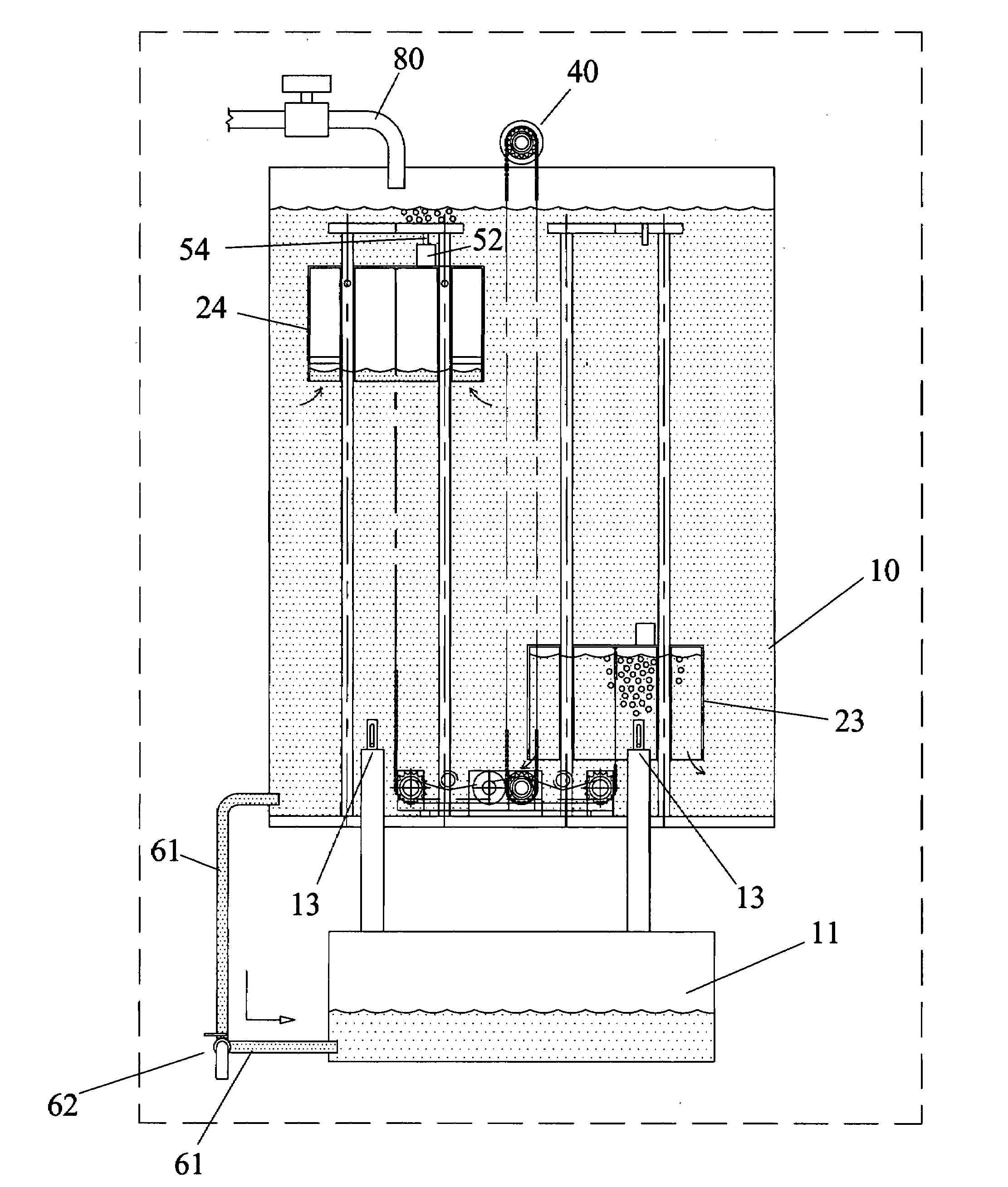
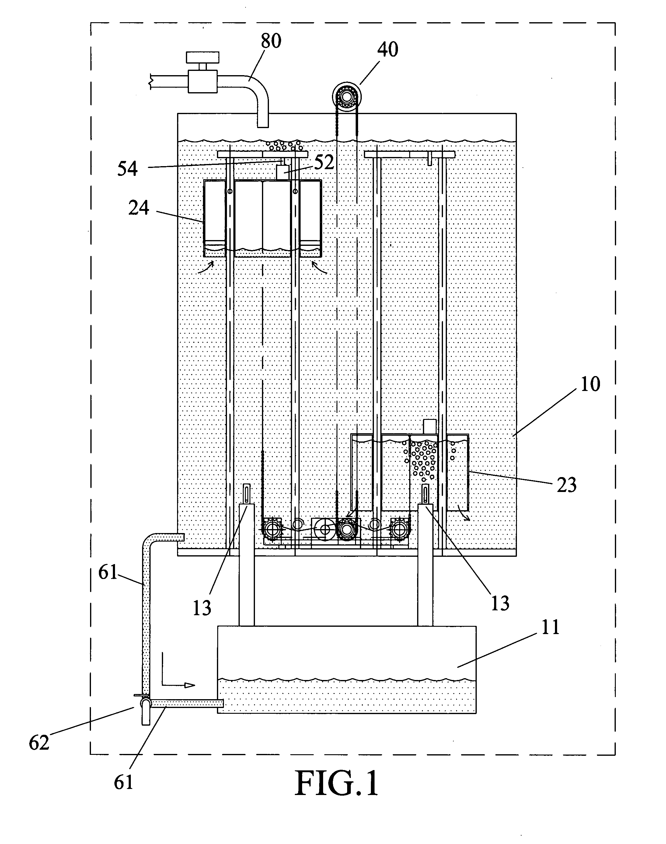
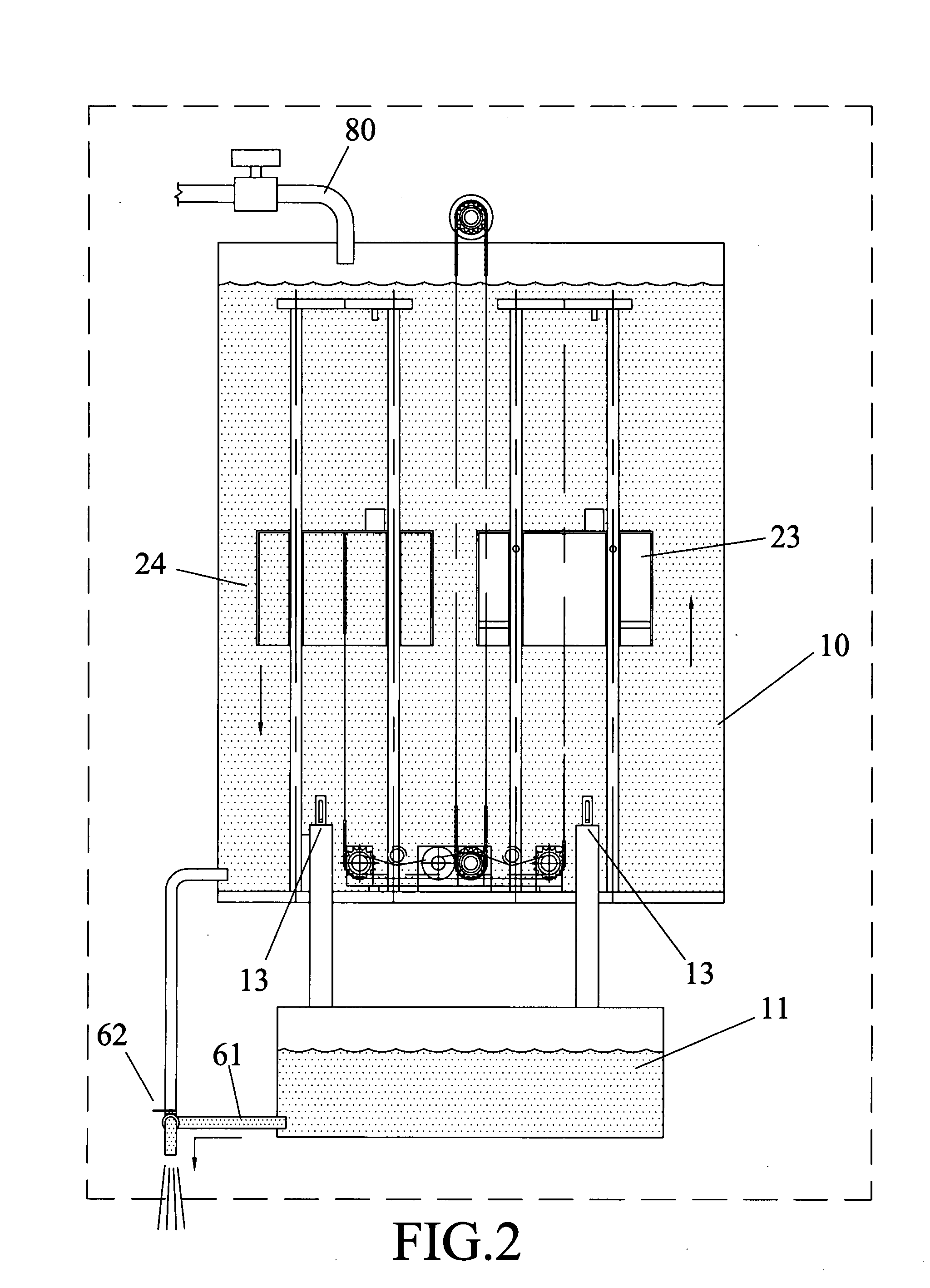
[0021]Referring to FIG. 1, the hydraulic buoyancy kinetic energy apparatus of the invention comprises a water tank 10, an air storage cylinder 11 located under the bottom of the water tank 10. A water supply source 80 provides water into the water tank 10 to keep the level of the water in the water tank 10 at high position. An upper level detector 101 and a low level detector 102 are connected to the water tank 10 so as to control the water supply source 80 to keep the water level at the high or full level. The water tank 10 includes an open top communicating with outside. A pipe 61 is connected between the bottom of the water tank 10 and the bottom of the air storage cylinder 11, a three-way valve 62 is connected to the pipe 61 so as to control the pipe 61 to communicate between the water tank 10 and the air storage cylinder 11. Two one-way valves 13 are located in the tank 10 and communicate with the air storage cylinder 11. Two buoys 23, 24 are located in the water tank 10 and mo...


PUM


Abstract

A hydraulic buoyancy kinetic energy apparatus includes a water tank filled with water and an air storage hood is merged in the water. Two buoys are movably connected to the two slippery pillars and a chain is connected with the two buoys via two chain wheels, two belt pulley sets and two engaged gears. One of the two gears drives a third chain wheel to drive an output shaft of an electric generating set. An air storage cylinder is connected with the water tank and air in the air storage cylinder can be pushed into the water tank to alternatively empty the two buoys which are alternatively moves up and down to drive the chain between the buoys and to activate the electric generating set.

Description

FIELD OF THE INVENTION[0001]The present invention relates an electric power generating device which is driven by a force generated by alternatively moving buoys in a water tank and a chain and a pulley set are connected between the two buoys.BACKGROUND OF THE INVENTION[0002]A conventional air buoyancy electric generator is disclosed in FIGS. 14 and 15 and generally employs an air compressor 01 to generate compressed air which is stored in a steel cylinder 03 through a duct 02 connected to between the compressor 01 and the steel cylinder 03. A valve 122 is connected to the duct 02 so as to control the compressed air into the steel cylinder 03. A water tank 04 filled with water and the compressed air in the steel cylinder 03 is discharged through a duct 05 to the water tank 04 from an air outlet 06 at the bottom of the water tank 04. A valve 222 is connected to the duct 05 so as to control the compressed air into the water tank 04. The discharged air is injected into an air chamber 08...

Claims


Application Information

Patent Timeline
Patent Type & Authority Applications(United States)
IPC IPC(8): F03B17/02
CPCF03B17/02Y02E10/20
Inventor TUNG, JUI-CHI
Owner TUNG JUI CHI
Why Eureka
Try Eureka