This helps you quickly interpret patents by identifying the three key elements:
Problems solved by technology
Method used
Benefits of technology
Benefits of technology
[0011]One or more embodiments of the invention provide an inexpensive vehicle lamp capable of making sure of a good side visibility during turning of a vehicle.
[0013]According to the vehicle lamp constructed as above, desired ones of a plurality of optical units are operated together in different strokes by driving the single actuator, so that a desired light distribution can be formed. As a result, a flexible light distribution change can be realized by the small and inexpensive lighting equipment configuration.
[0015]According to the vehicle lamp constructed in this manner, for example, only a dispersing zone (middle luminous intensity area) can be brought into the turning direction of the vehicle, while adequately holding the positions of the hot zone (high luminous intensity area) and an middle zone (middle luminous intensity area), so that the overall light distribution is swiveled. As a result, fine formation of a light distribution pattern PL can be attained.
[0017]According to the vehicle lamp constructed in this manner, when the cam grooves that are respectively engaged with the driven shafts of the optical units are formed to have desired offset profiles, it can be easy to individually set the optical units to desired turning angles. Also, when a plurality of sets of the first cam, the second cam, and the third cam formed by different cam grooves are previously prepared, a plurality of variations of the lighting equipment specifications applied to different angle controls can be selectively set easily.
[0019]According to the vehicle lamp constructed in this manner, the intermediate link and the optical unit side link with which the force application axes of the optical units are respectively engaged are relatively turned in predetermined turning positions by the interlock separating mechanism. Therefore, it can be easy to independently set individual optical units to the desired turning angles. Also, since the intermediate link and the optical unit side link can be constructed by a thin link plate, a swiveling mechanism that is lighter in weight than the configuration using a large number of gears can be realized.
[0020]According to the vehicle lamp of one or more embodiments of the present invention, the swivel driving mechanism swivels a plurality of optical units together in different strokes by one actuator. Therefore, desired ones of a plurality of optical units are driven together in different strokes, and thus a desired light distribution can be formed. As a result, according to the vehicle lamp of the present invention, a flexible light distribution change that can make sure of a good side visibility in the turning of the vehicle can be realized by a small inexpensive lighting equipment configuration.
Problems solved by technology
Since an irradiation light emitted from a headlight of a vehicle illuminates a front center portion of the road, the headlight cannot often get hold of enough illumination range in front of a traveling direction during going around a curve, turning to the right or left, changing the lane, or the like.
Accordingly, the enough illumination range cannot be ensured ahead of the turning direction of the vehicle during a left or right turn at an intersection, and the like.
As a result, it is considered that the effect of the swivel system cannot be sufficiently achieved.
However, in this system, an overall lighting equipment may be increased in size and becomes expensive.
Method used
Image
Click on the blue label to locate the original text in one second.
Reading with bidirectional positioning of images and text.
Examples
first embodiment
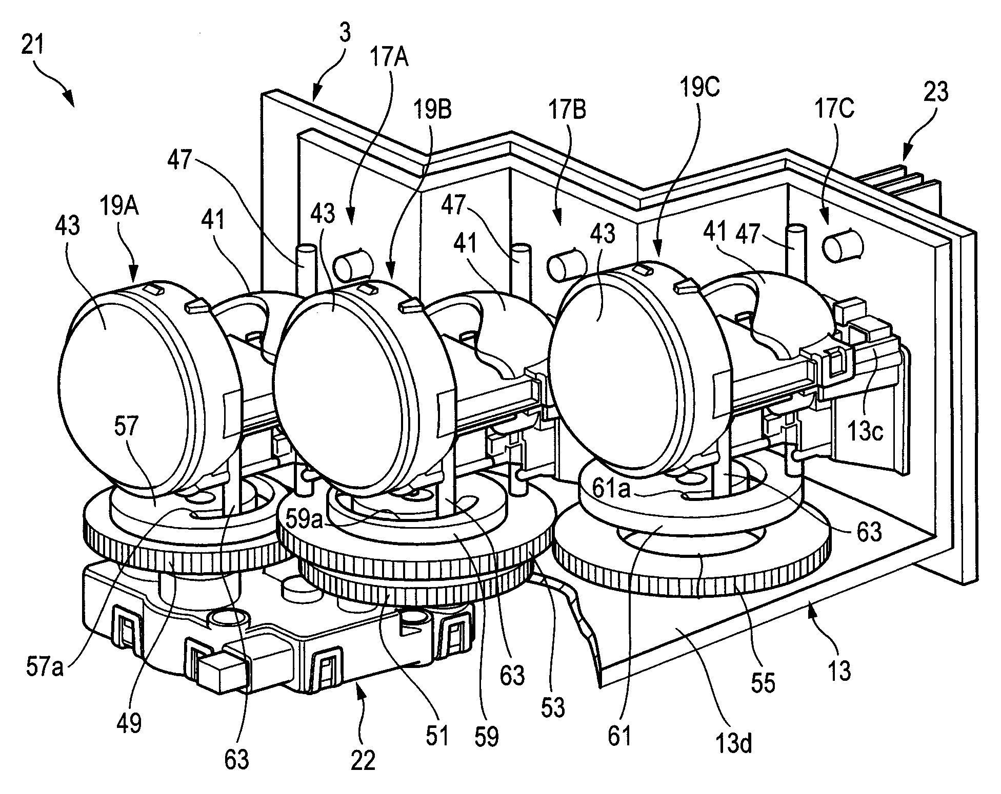
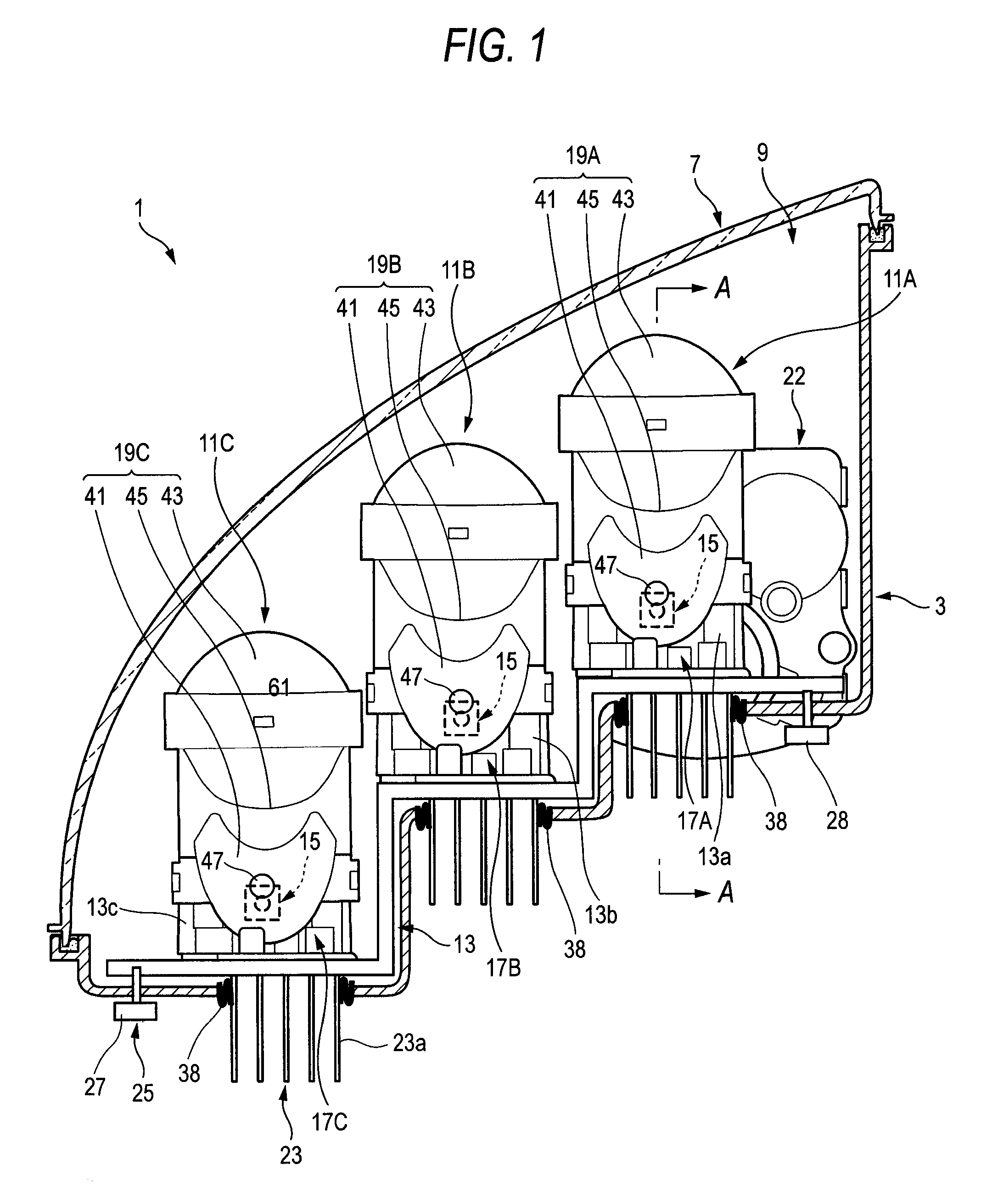
[0040]As shown in FIG. 1, a vehicle lamp 1 includes lamp units in a lighting chamber 9. This lighting chamber 9 is constructed by a lamp body 3 whose front side is opened, and a transparent front cover 7 fitted to the front opening portion.
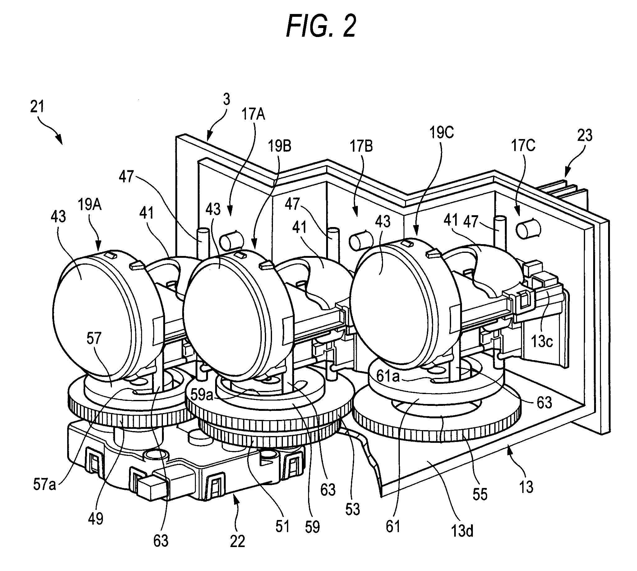
[0041]The vehicle lamp of the present embodiment consists of a plurality of lamp units 11A, 11B, 11C (three in the present embodiment). These lamp units 11A, 11B, 11C are sequentially arranged from the inner side to the outer side in the vehicle width direction (in the present embodiment, the configuration of the vehicle lamp arranged on the left side of the vehicle body is shown).
[0042]These lamp units 11A, 11B, 11C include light source units 17A, 17B, 17C in which a light emitting element 15 is respectively supported by supporting portions 13a, 13b, 13c of a unit mounting portion 13, and optical units 19A, 19B, 19C for respectively emitting the light from the light emitting element 15 ahead of the lighting equipment. Also, these lamp units 11A,...
second embodiment
[0096]Next, a link-type driving system of the optical units 19A, 19B, 19C will be explained hereunder.
[0097]FIG. 14 is a plan view of the link portion all optical units of which are directed outward by 15 degree, FIG. 15 is a plan view of the link portion two inner optical units of which are directed outward by 15 degree and two outer optical units of which are directed outward by 30 degree, and FIG. 16 is a plan view of a link portion one inner optical unit of which is directed inward by 10 degree and two outer optical units of which are directed in a straight-ahead direction.
[0098]All the optical units 19A, 19B, 19C are normally directed in the straight ahead direction, as shown in FIG. 11. Here, for example, when the output shaft 103 of the actuator 22 is turned leftward by 15 degree in response to the left turn of the steering wheel, the actuator link 105 is turned leftward by 15 degree and also the intermediate link 111 engaged with the pressing shaft 109 is turned leftward by...
PUM
Abstract
A vehicle lamp is provided with a plurality of lamp units respectively including light sources, and optical units for emitting light from the light sources ahead of the lamp unit, and a driving unit configured to swivel the plurality of optical units in different strokes.
Description
[0001]This application claims foreign priority from Japanese Patent Application No. 2007-116537 filed on Apr. 26, 2007, the entire contents of which are hereby incorporated by reference.BACKGROUND OF THE INVENTION[0002]1. <Field of the Invention>[0003]The present invention relates to a vehicle lamp having a plurality of lamp units and, more particularly, a vehicle lamp equipped with a swiveling mechanism for changing an illumination direction and an illumination range of a light source in answer to a traveling condition.[0004]2. <Background Art>[0005]Since an irradiation light emitted from a headlight of a vehicle illuminates a front center portion of the road, the headlight cannot often get hold of enough illumination range in front of a traveling direction during going around a curve, turning to the right or left, changing the lane, or the like. As the vehicle lamp that can satisfactorily get hold of illumination range of the irradiation light during going around a cur...
Claims
Application Information
Patent Timeline
Application Date:The date an application was filed.
Publication Date:The date a patent or application was officially published.
First Publication Date:The earliest publication date of a patent with the same application number.
Issue Date:Publication date of the patent grant document.
PCT Entry Date:The Entry date of PCT National Phase.
Estimated Expiry Date:The statutory expiry date of a patent right according to the Patent Law, and it is the longest term of protection that the patent right can achieve without the termination of the patent right due to other reasons(Term extension factor has been taken into account ).
Invalid Date:Actual expiry date is based on effective date or publication date of legal transaction data of invalid patent.

