Method and System With Focus Control for Scanning an Information Carrier

a technology of information carrier and focus control, which is applied in the direction of data recording, instruments, optical recording heads, etc., can solve the problems of inability to easily and efficiently use optical storage solutions, the known applications of optical storage solutions are not robust to shocks, and the focus of light spots is not perfect, so as to achieve accurate and reliable positioning of information carriers

Inactive Publication Date: 2008-10-30
KONINKLIJKE PHILIPS ELECTRONICS NV
View PDF4 Cites 13 Cited by
  • Summary
  • Abstract
  • Description
  • Claims
  • Application Information

AI Technical Summary

Benefits of technology

[0034]Thus, it is an object of the present invention to provide a method and system for accurately and reliably positioning an information carrier with respect to an array of light spots in a scanning and / or writing apparatus.

Problems solved by technology

However, due to the large amount of moving elements in the drives, known applications using optical storage solutions are not robust to shocks when performing read / write operations, considering the required stability of said moving elements during such operations.
As a consequence, optical storage solutions cannot easily and efficiently be used in applications which are subject to shocks, such as in portable devices.
In practice it may occur that the light spots are not perfectly focussed, to the detriment of the data reading in the data area 105.
However, the end signal is unidirectional in the sense that it does not give information on whether a negative or positive correction of the position of the data card is necessary.
The positioning of the information carrier is thus not reliable.

Method used


Image

  • Method and System With Focus Control for Scanning an Information Carrier
  • Method and System With Focus Control for Scanning an Information Carrier
  • Method and System With Focus Control for Scanning an Information Carrier

Examples


Embodiment Construction

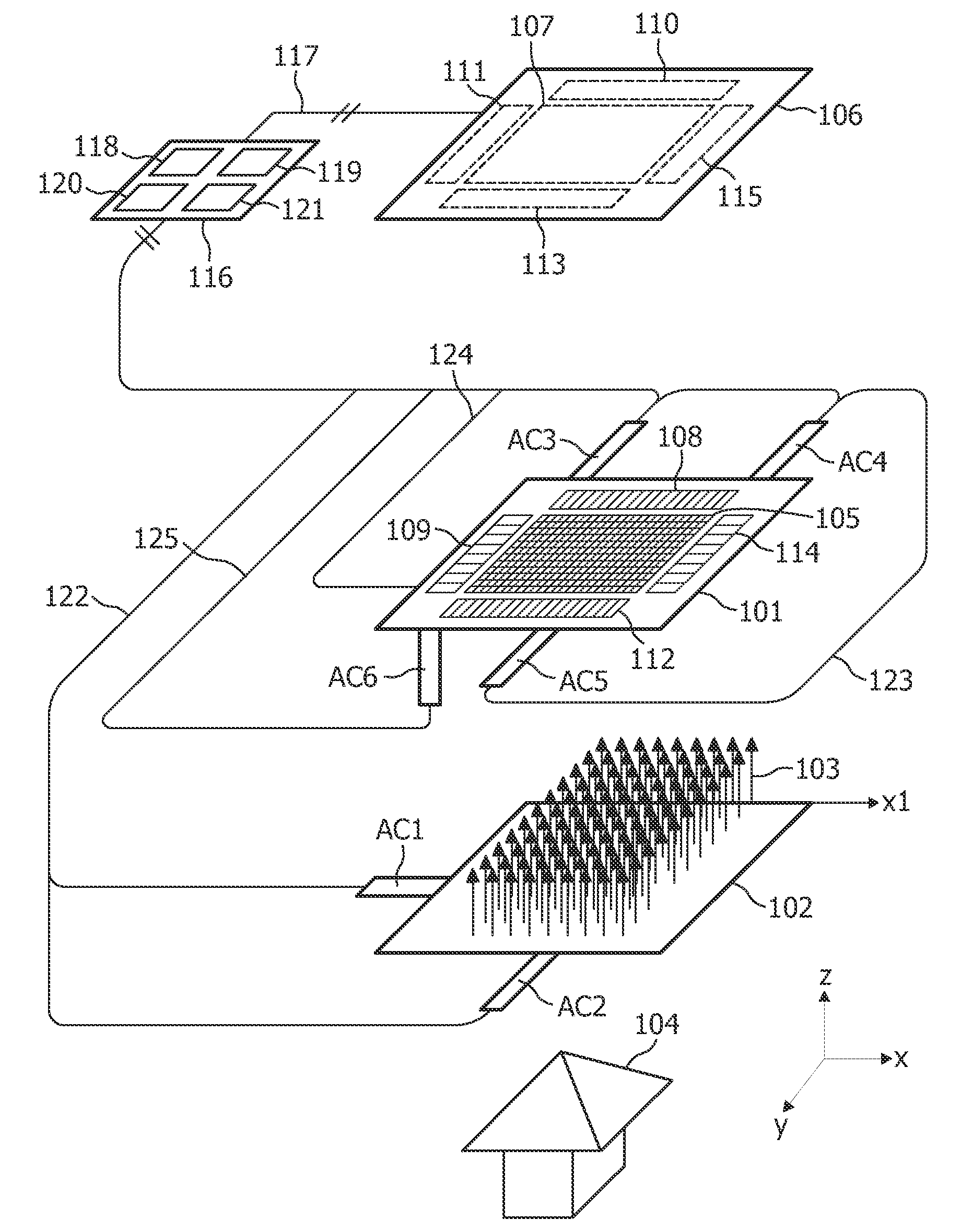
[0062]By way of background, and referring to FIG. 6 of the drawings, there is depicted the top view of an information carrier 101 comprising a first periodic structure 108 and a second periodic structure 109 placed perpendicularly. Each periodic structure is made of parallel stripes having a period referred to as “s” (it is noted that the first period of the first periodic structure 108 and the period of the second periodic structure 109 could be different). The data area 105 is made of adjacent macro-cells (squares in bold lines), each macro-cell comprising a set of elementary data areas (sixteen elementary data areas are represented in this example). Each macro-cell is intended to be scanned by one light spot.

[0063]The Moiré effect is an optical phenomenon which occur when an input image with a structure having a period s (i.e. the periodic structure 108 or 109 in the present case) is sampled with a periodic sampling grid having a period p (i.e. the periodic array of light spots 1...


PUM

PropertyMeasurementUnit
diameteraaaaaaaaaa
distanceaaaaaaaaaa
phase/amplitudeaaaaaaaaaa

Abstract

The invention relates to a method and system for reading data on a data layer (105) of an information carrier (101) comprising one or more servo marks (108, 109) positioned relative to said data layer (105), the system comprising: probe array generation means (104, 102) for generating a probe array comprising an array of light spots (103) intended to be applied to said information carrier (101) so as to generate output beams representative of said one or more servo marks (108, 109) and said data, wherein the distance between the focal point of one or more light spots of a portion of said probe array and a respective portion of said information carrier corresponding to at least one servo mark is different to the distance between the focal points of the light spots of the rest of the probe array and the rest of said information carrier; an image sensor (106) for receiving said output beams and generating a corresponding image; means (116) for deriving a contrast value in respect of at least of a portion of said image corresponding to said at least one servo mark (108, 109) and generating a control signal (125) derived from said contrast value, said control signal (125) being for application to actuation means (AC6) for adjusting the distance between said information carrier (101) and said array of light spots (103).

Description

FIELD OF THE INVENTION[0001]The invention relates to a method and system with focus control for scanning an information carrier[0002]The invention has applications in the field of optical data storage and microscopy.BACKGROUND OF THE INVENTION[0003]The use of optical storage solutions is nowadays widespread for content distribution, for example in storage systems based on the DVD (Digital Versatile Disc) standards. Optical storage has a big advantage over hard-disc and solid-state storage in that the information carriers are easy and cheap to replicate.[0004]However, due to the large amount of moving elements in the drives, known applications using optical storage solutions are not robust to shocks when performing read / write operations, considering the required stability of said moving elements during such operations. As a consequence, optical storage solutions cannot easily and efficiently be used in applications which are subject to shocks, such as in portable devices.[0005]New op...

Claims


Application Information

Patent Timeline
Patent Type & Authority Applications(United States)
IPC IPC(8): G11B7/00
CPCG11B7/0033G11B7/0908G11B7/0938G11B7/12
Inventor BAKKER, LEVINUS PIETER
Owner KONINKLIJKE PHILIPS ELECTRONICS NV
Why Eureka
Try Eureka