Faraday assembly of ion implantation apparatus

a technology of ion implantation and assembly, which is applied in the direction of heat measurement, separation processes, instruments, etc., can solve the problems of excessive current draw, excessive load applied to the motor, and excessive current draw

Inactive Publication Date: 2006-05-25
SAMSUNG ELECTRONICS CO LTD
View PDF14 Cites 10 Cited by
  • Summary
  • Abstract
  • Description
  • Claims
  • Application Information

AI Technical Summary

Benefits of technology

[0009] More specifically, an object of the present invention is to provide a Faraday assembly of an ion implantation apparatus that can precisely and reliably position a Faraday cup within a vacuum chamber of the apparatus.
[0010] Another object of the present invention is to provide a Faraday assembly of an ion implantation apparatus having an assist for the motor of the assembly so that the motor is not overloaded during an operation of the assembly in which a component of the assembly is being drawn out of a vacuum chamber by the motor.

Problems solved by technology

However, a relatively large load is applied to the power means by the vacuum in the vacuum chamber when the Faraday cup is retracted within the vacuum chamber.
In this case, the motor is overloaded and draws excessive current, whereupon the Faraday cup is positioned at an incorrect location within the vacuum chamber.

Method used


Image

  • Faraday assembly of ion implantation apparatus
  • Faraday assembly of ion implantation apparatus
  • Faraday assembly of ion implantation apparatus

Examples


Embodiment Construction

[0027] Embodiments of a Faraday assembly of an ion implantation apparatus according to the present invention will be described in detail hereinafter with reference to the attached drawings.

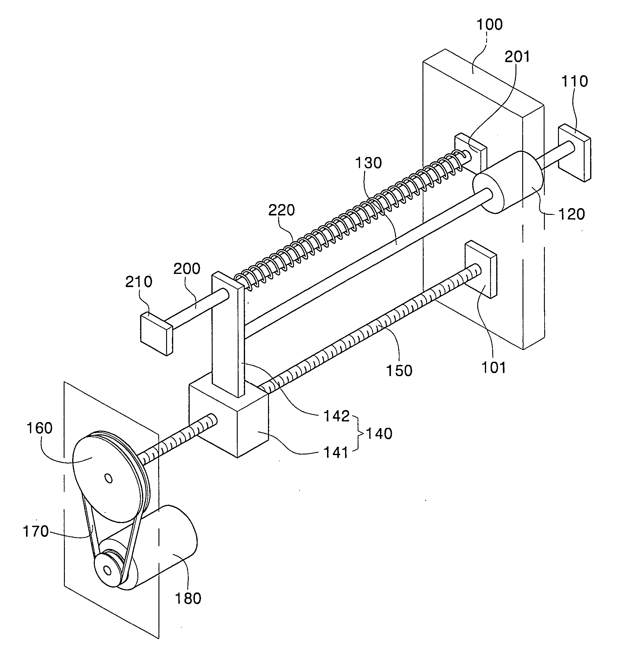
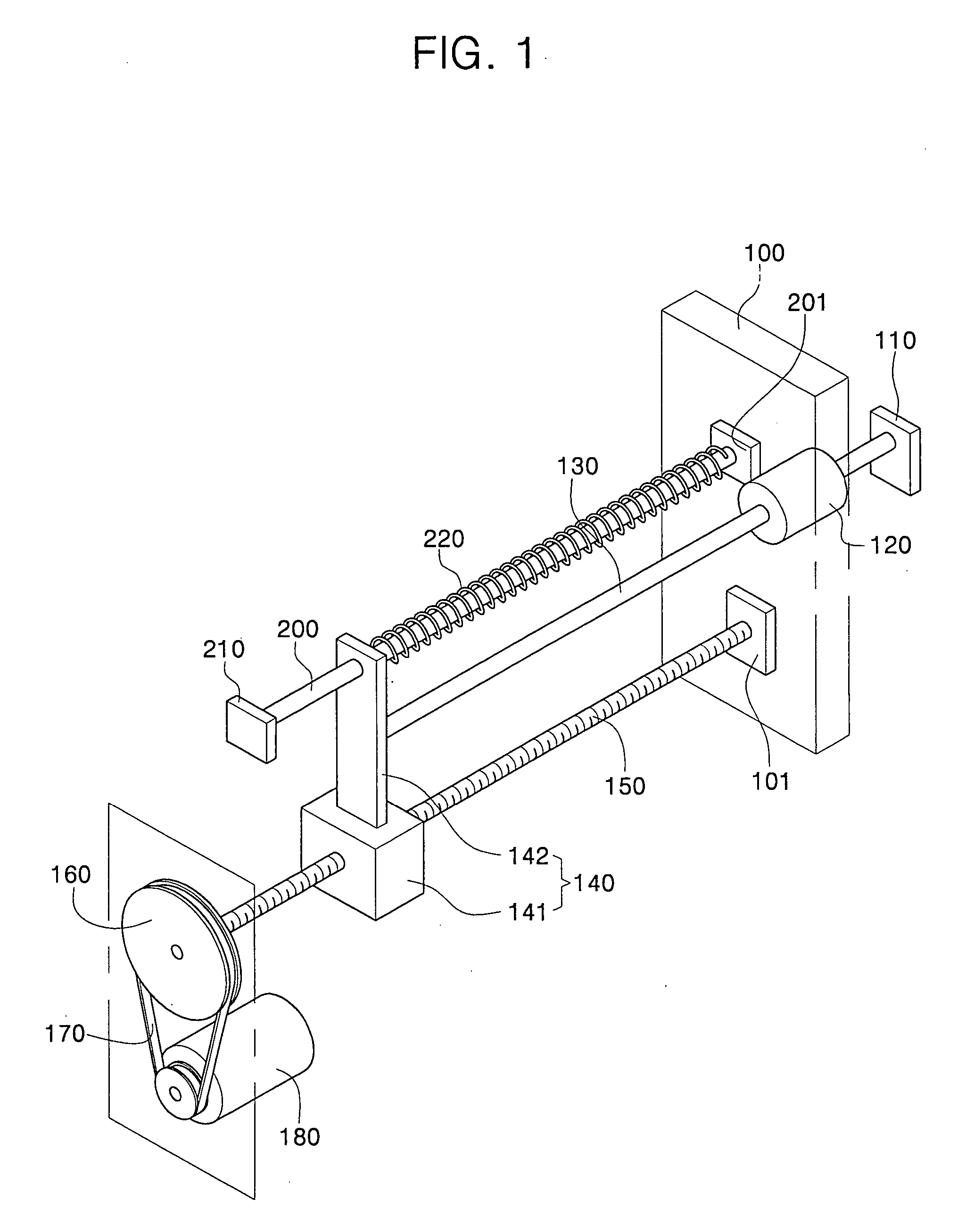
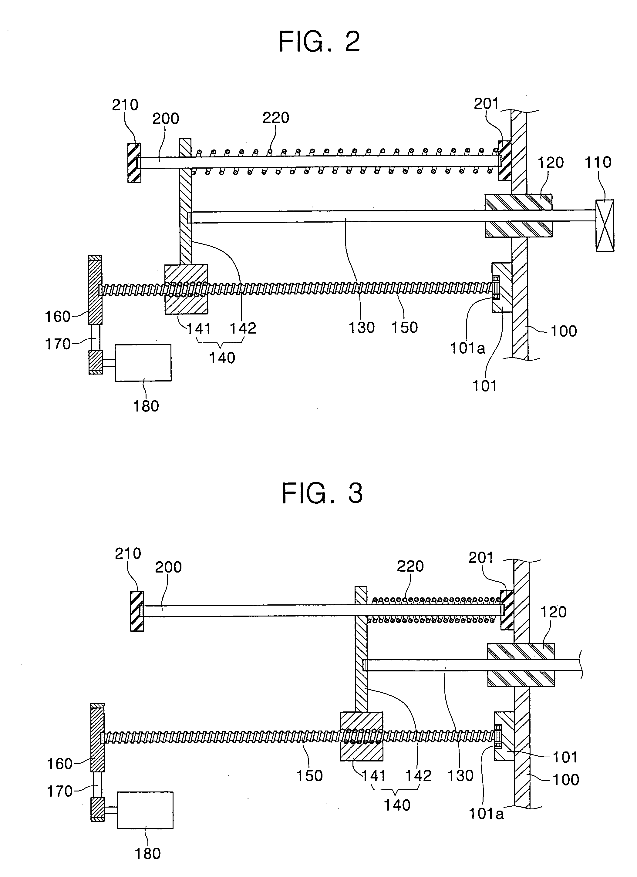
[0028] Referring to FIGS. 1-3, a first embodiment of the Faraday assembly of the ion implantation apparatus according to the present invention includes: a Faraday cup 110 located in a vacuum chamber 100 which is maintained at a low vacuum pressure of about 10−3 torr; and a driving shaft 130 extending into the vacuum chamber 100 through a wall thereof. One end of the driving shaft 130 is connected to the Faraday cup 110 within vacuum chamber 100 and the other end of the driving shaft 130 is disposed outside the vacuum chamber 100.

[0029] Also, the wall of the vacuum chamber 100 is provided with an annular seal 120 for preventing loss of the vacuum pressure within the vacuum chamber 100 and for preventing external air from entering the vacuum chamber 100. The driving shaft 130 is centered in the se...


PUM

PropertyMeasurementUnit
vacuum pressureaaaaaaaaaa
forceaaaaaaaaaa
poweraaaaaaaaaa

Abstract

A Faraday assembly of an ion implantation apparatus includes a Faraday cup in a vacuum chamber, a driving shaft to which the Faraday cup is connected, a motor for inserting the driving shaft further into and drawing the driving shaft out of the vacuum chamber to cause the Faraday cup to advance and retreat within the chamber, and an auxiliary supplier of power for exerting a force that acts on the driving shaft as the driving shaft is being extracted by the motor from the vacuum chamber. Therefore, the force of suction, due to a pressure difference between interior and exterior of the vacuum chamber, is prevented from overloading the motor as the Faraday cup retreats within the vacuum chamber. As a result, the Faraday cup is positioned precisely and efficiently within the vacuum chamber.

Description

BACKGROUND OF THE INVENTION [0001] 1. Field of the Invention [0002] The present invention relates to an ion implantation apparatus. More particularly, the present invention relates to a Faraday assembly of an ion implantation apparatus, for moving a Faraday cup within a vacuum chamber of the apparatus. [0003] 2. Description of the Related Art [0004] Generally, ion implantation apparatus have been used for a long time in the manufacturing of semiconductor devices. In particular, an ion implantation apparatus forcibly implants ions into a selected region of a wafer made of silicon, for example. The ion implantation apparatus includes a particle accelerator to accelerate the ions as a beam towards the wafer. The ions collide with the silicon atoms of the wafer, thereby gradually losing energy, and stop at a certain depth in the crystal lattice structure of the silicon. [0005] The ion implantation apparatus also includes a Faraday cup. The Faraday cup functions as a sensor for measuring...

Claims


Application Information

Patent Timeline
Patent Type & Authority Applications(United States)
IPC IPC(8): G01K1/08
CPCG01K1/08G01K11/20H01J37/317H01J37/3171H01J37/16H01L21/265H01J2237/24405H01J2237/31701
Inventor HWANG, SUN-HOPARK, SANG-KUK
Owner SAMSUNG ELECTRONICS CO LTD
Why Eureka
Try Eureka