Ultrasonic image processing apparatus and ultrasonic image processing method

a processing apparatus and ultrasonic technology, applied in the field of ultrasonic image processing apparatus, can solve the problems of reducing the display size per image, difficult for an observer to simultaneously grasp all images, and inability to implement chronological observation of locally the same region, etc., to achieve accurate and rapid acquisition of three-dimensional motion information.

Active Publication Date: 2008-10-30
TOSHIBA MEDICAL SYST CORP
View PDF9 Cites 47 Cited by
  • Summary
  • Abstract
  • Description
  • Claims
  • Application Information

AI Technical Summary

Benefits of technology

[0011]The present invention has been made in consideration of the above situation, and has as its object to provide an ultrasonic image processing apparatus and ultr

Problems solved by technology

The following problems arise in the conventional method of analyzing three-dimensional motion information.
For this reason, the conventional technique cannot implement chronological observation of locally the same region (tissue).
As a result, the number of image

Method used


Image

  • Ultrasonic image processing apparatus and ultrasonic image processing method
  • Ultrasonic image processing apparatus and ultrasonic image processing method
  • Ultrasonic image processing apparatus and ultrasonic image processing method

Examples


first embodiment

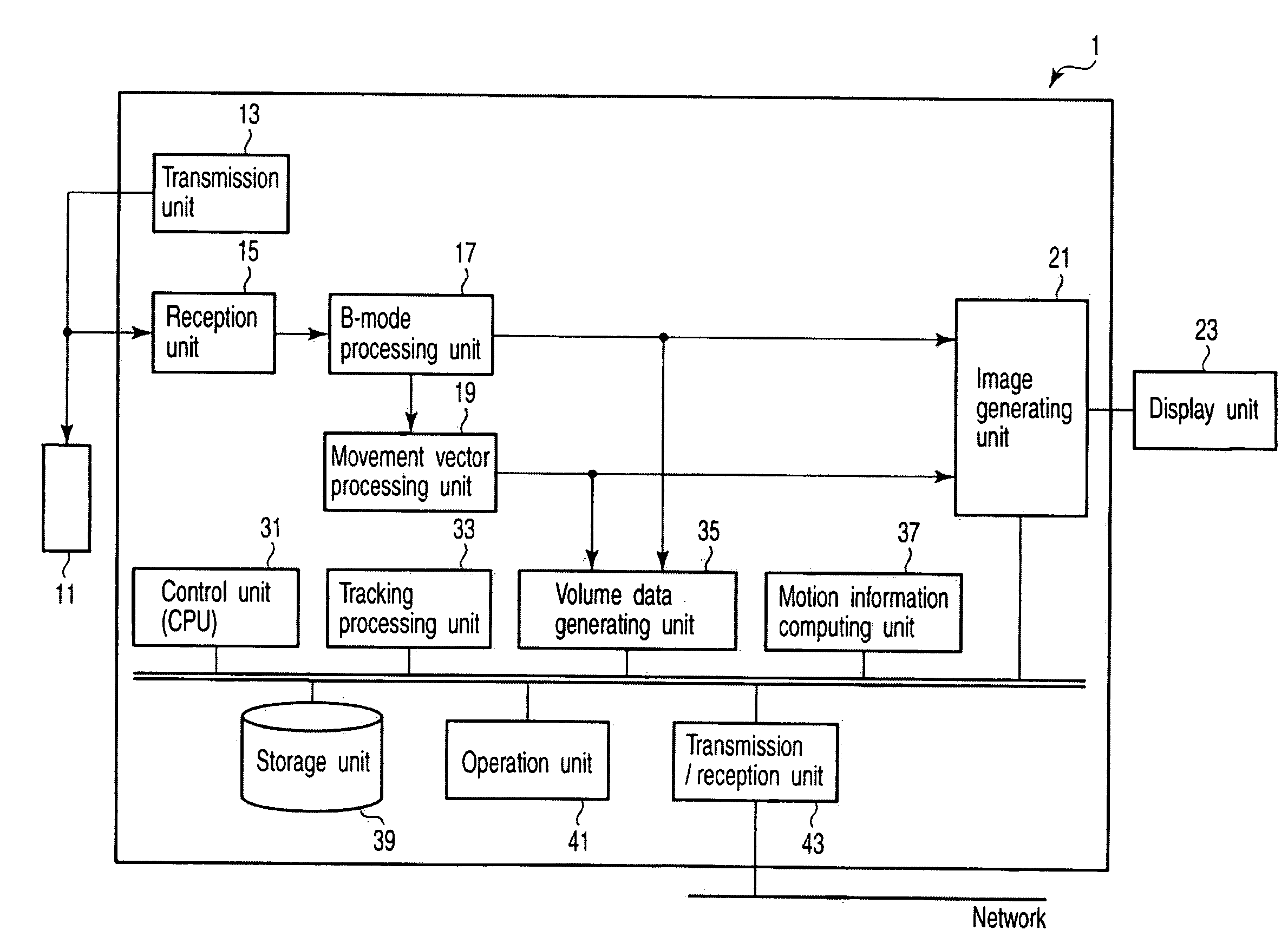
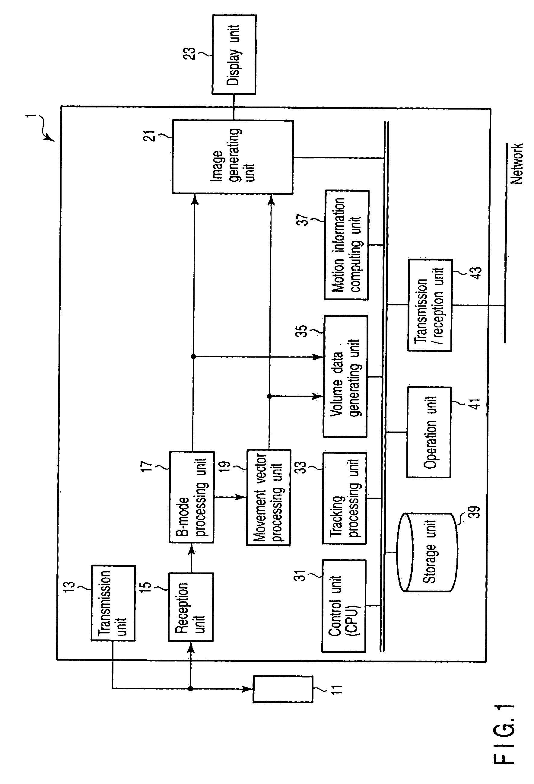
[0038]FIG. 1 is a block diagram showing the arrangement of an ultrasonic diagnosis apparatus 1 according to the first embodiment. The ultrasonic diagnosis apparatus 1 comprises an ultrasonic probe 11, a transmission unit 13, a reception unit 15, a B-mode processing unit 17, a movement vector processing unit 19, an image generating unit 21, a display unit 23, a control unit (CPU) 31, a tracking processing unit 33, a volume data generating unit 35, a motion information computing unit 37, a storage unit 39, an operation unit 41, and a transmission / reception unit 43. Note that when the present invention is applied to an ultrasonic image processing apparatus, the constituent elements of the apparatus are those enclosed by the dotted line in FIG. 1.

[0039]The ultrasonic probe 11 includes a plurality of piezoelectric transducers which generate ultrasonic waves on the basis of driving signals from the transmission unit 12 and convert reflected waves from an object to be examined into electri...

example 1

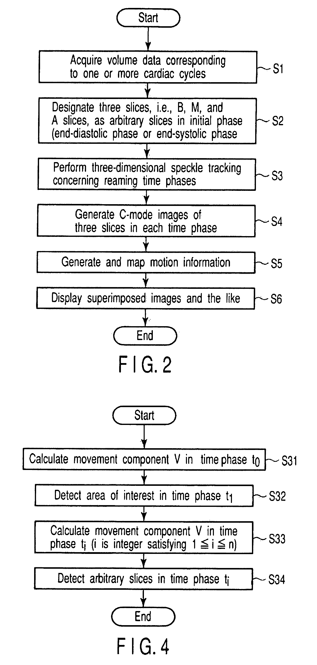
[0061]The tracking method according to this example obtains a movement component V by projecting movement vectors at the respective positions of tissues existing on the respective slices in the normal direction and averaging the vectors, and tracking an arbitrary slice in each time phase by using the movement component.

[0062]FIG. 4 is a flowchart showing a sequence of arbitrary slice tracking processing in step S3. As shown in FIG. 4, first of all, movement component V=Vz,mean(t0) in the initial time phase t0 is calculated by averaging only normal-direction components (projection components in the normal direction shown by “z” in FIG. 4) of movement vectors of the respective tissues (i.e., the positions of tissues contained in the respective surfaces) on the B, M, and A surfaces set for the volume data of the initial time phase (step S31).

[0063]The B, M, and A surfaces set in the initial time phase are translated by movement component V=Vz,mean(t0) along the normal direction, and ca...

example 2

[0068]The tracking method according to this example obtains the movement component V by averaging movement vectors at the respective positions of tissues existing in set arbitrary slices (without projection in the normal direction) and tracks arbitrary slices in each time phase by using the obtained component.

[0069]Referring to FIG. 4, first of all, movement component V=Vmean(t0) is calculated by averaging the movement vectors of the respective myocardials (i.e., the respective positions on tissues included in the respective surfaces) in the B, M, and A surfaces set for the volume data of the initial time phase (step S31).

[0070]The B, M, and A surfaces set in the initial time phase are translated by movement component V=Vmean(t0) to set the B, M, and A surfaces in the time phase t1 (step S32).

[0071]Movement component V=Vmean(ti) in the time phase ti (i is an integer satisfying 2≦i≦n) is calculated by averaging the movement vectors of the respective myocardials on the B, M, and A sur...


PUM


Abstract

Three slices, i.e., Basal, Mid, and Apical slices, which correspond to clinically useful ASE segmentation are designated, and the positions of the three slices are tracked through at least one cardiac cycle by performing three-dimensional speckle tracking in the remaining time phases. Three C-mode projection images concerning the tracked positions are reconstructed. In addition, arbitrary myocardial wall motion parameters at the tracked positions are computed and displayed upon being superimposed on C-mode images or projected/displayed on a polar map. As a C-mode projection image method, one of the following techniques can be used detecting and projecting only movement components perpendicular to slices determined in an initial time phase, detecting and projecting average movement components of the respective walls, and tracking and projecting each myocardial position. The obtained C-mode images are simultaneously displayed together with markers indicating the positions of long-axis images and C-mode images.

Description

CROSS-REFERENCE TO RELATED APPLICATIONS[0001]This application is based upon and claims the benefit of priority from prior Japanese Patent Application No. 2007-117314, filed Apr. 26, 2007, the entire contents of which are incorporated herein by reference.BACKGROUND OF THE INVENTION[0002]1. Field of the Invention[0003]The present invention relates to an ultrasonic image processing apparatus and the like which can dynamically track a target locomotive tissue by using, for example, MPR images typified by C-mode tomograms in accordance with the motion of the tissue, and display, in a predetermined form, the motion information of the tissue computed by using the tracking result.[0004]2. Description of the Related Art[0005]An ultrasonic diagnosis technique can display, in real time, how a heart beats or a fetus moves, with simple operation of bringing an ultrasonic probe into contact with the body surface. In addition, this technique offers a high level of safety, and hence can be repeated...

Claims


Application Information

Patent Timeline
IPC IPC(8): A61B5/00
CPCA61B8/08A61B8/5246A61B8/523A61B8/14
Inventor ABE, YASUHIKOKAWAGISHI, TETSUYA
Owner TOSHIBA MEDICAL SYST CORP
Why Eureka
Try Eureka