
Gas turbine engine blade tip clearance apparatus and method

Active Publication Date: 2008-10-30
RAYTHEON TECH CORP
View PDF19 Cites 50 Cited by
  • Summary
  • Abstract
  • Description
  • Claims
  • Application Information

AI Technical Summary

Benefits of technology

[0013]In accordance with another aspect of the present disclosure, a method for controlling blade tip clearance within a gas turbine engine broadly comprises providing a compressor having at least one first rotor assembly, each first rotor assembly having a plurality of blades with each blade having a blade tip, at least one first stator assembly disposed adjacent at least one first rotor assembly, and a shroud having at least one blade seal surfaces disposed radially outside of at least one first rotor assembly, wherein the blade tips in each of at least one first rotor assembly has a mating geometry with at least one of at least one blade seal surface, and a clearance distance extending between the blade tips and the blade seal surfaces; providing a turbine having at least one second rotor assembly, each second rotor assembly having a plurality of blades with eac

Problems solved by technology

A problem with an abradable system is that it is not adjustable once the seal is abraded.
A problem with prior art active clearance systems is their response time.
Such systems are still subject to the casing's thermal response time, and the mismatch of the casing's thermal response to the rotor disk's thermal response.
The deceleration causes a decrease in the centrifugal loading on the rotor assembly and rapid cooling of the blades, which results in a decrease in the mechanical growth of the rotor assembly.
If, however, a sharp acceleration is performed between positions G and H, the clearance in a prior art compressor will decrease significantly.

Method used


Image

  • Gas turbine engine blade tip clearance apparatus and method
  • Gas turbine engine blade tip clearance apparatus and method
  • Gas turbine engine blade tip clearance apparatus and method

Examples


Embodiment Construction

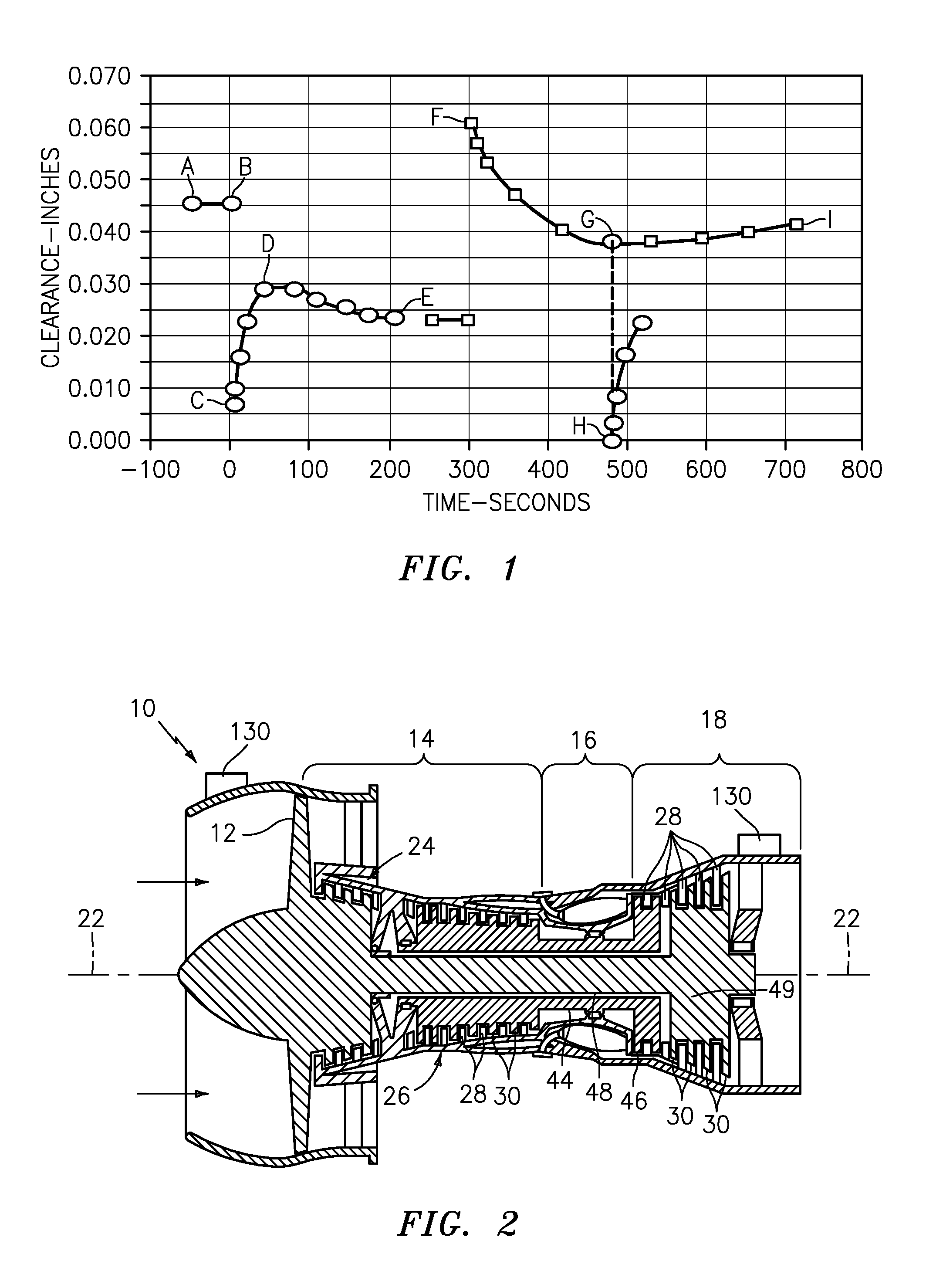
[0028]Referring to FIGS. 2 and 3, a gas turbine engine 10 is diagrammatically shown that includes a fan section 12, a compressor section 14, a combustor section 16, and a turbine section 18. The engine 10 has an axially extending centerline 22. Ambient air enters the engine 10 through the fan section 12. A fraction of that air subsequently travels through the compressor, combustor, and turbine sections 14, 16, 18 as core gas flow before exiting through a nozzle.

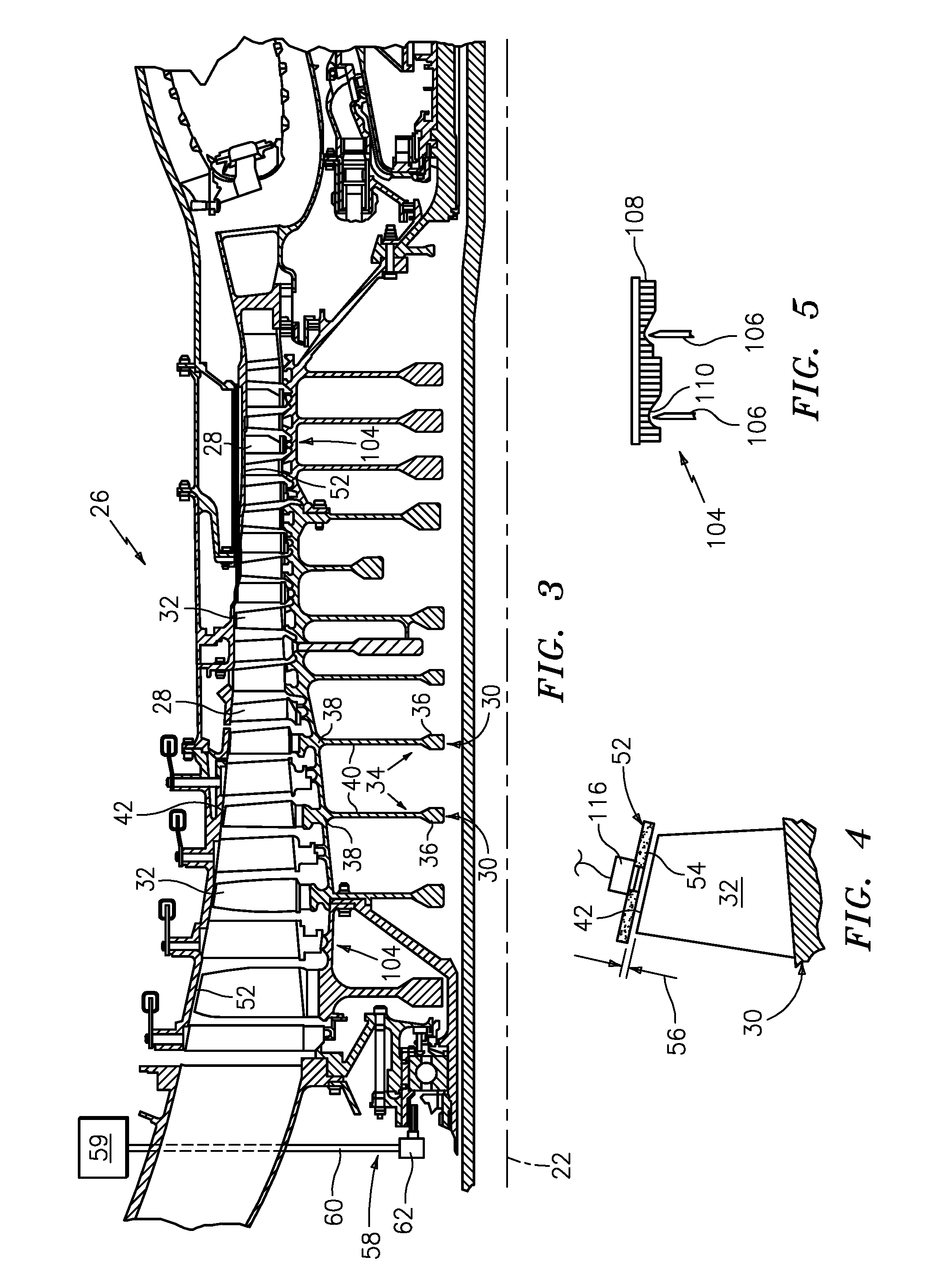
[0029]The compressor 14 may be a single unit or may be sectioned into a low-pressure compressor 24 and a high-pressure compressor 26. Both the low-pressure compressor 24 and the high-pressure compressor 26 (or the single compressor embodiment) include a plurality of stator assemblies 28 and rotor assemblies 30. The stator assemblies 28 include a plurality of segments, each having one or more stator vanes disposed between an inner platform and an outer platform. The segments of each stator assembly 28 collectively form an annu...


PUM


Abstract

A method for controlling blade tip clearance within a gas turbine engine includes the steps of providing a compressor having at least one first rotor assembly, each first rotor assembly having a plurality of blades with each blade having a blade tip, at least one first stator assembly disposed adjacent at least one first rotor assembly, and a shroud having at least one blade seal surface disposed radially outside of at least one first rotor assembly, wherein the blade tips in each of at least one first rotor assembly has a mating geometry with at least one of at least one blade seal surfaces, and a clearance distance extending between the blade tips and the blade seal surfaces; providing a turbine having at least one second rotor assembly, each second rotor assembly having a plurality of blades with each blade having a blade tip, at least one second stator assembly disposed adjacent at least one second rotor assembly, and the shroud having at least one blade seal surface disposed radially outside of at least one second rotor assembly, wherein the blade tips in each of at least one second rotor assembly has a mating geometry with at least one of at least one blade seal surfaces, and a clearance distance extending between the blade tips and the blade seal surfaces; providing an actuator selectively operable to move at least one rotor assembly relative to the shroud; providing an electronic engine controller having a control logic for operating the actuator; and moving at least one first rotor assemblies and at least one second rotor assembly relative to the shroud using the actuator at a response rate according to the control logic to alter the clearance distance.

Description

CROSS REFERENCE TO RELATED APPLICATIONS[0001]This application is a continuation-in-part of prior U.S. patent application Ser. No. 11 / 253,235, filed on Oct. 17, 2005, which is a continuation-in-part of U.S. patent application Ser. No. 11 / 025,435 filed on Dec. 29, 2004, which issued as U.S. Pat. No. 7,341,426 on Mar. 11, 2008.FIELD OF THE DISCLOSURE[0002]The present disclosure relates to gas turbine engines in general, and to blade tip clearance therein in particular.BACKGROUND OF THE DISCLOSURE[0003]In an axial flow gas turbine engine, air is compressed in a compressor section, mixed with fuel and combusted in a combustor section, and expanded through a turbine section that, via one or more shafts, drives the compressor section. The overall efficiency of such engines is a function of, among other factors, the efficiency with which the compressor section compresses the air and the efficiency with which the turbine expands the products of combustion. The compressor section typically in...

Claims


Application Information

Patent Timeline
IPC IPC(8): F04D29/56
CPCF01D11/20F01D11/22F01D11/24Y02T50/671F04D29/052Y02T50/60
Inventor SCHWARZ, FREDERICK M.SMITH, J. WALTER
Owner RAYTHEON TECH CORP
Learn More