Ultrasonic diagnostic apparatus and image display method thereof

a diagnostic apparatus and ultrasonic technology, applied in the field of ultrasonic diagnostic apparatus, can solve the problems of difficult to observe the deformation of the blood vessel caused, etc., and achieve the effect of easy deformation determination

Active Publication Date: 2008-10-30
TOSHIBA MEDICAL SYST CORP
View PDF9 Cites 36 Cited by
  • Summary
  • Abstract
  • Description
  • Claims
  • Application Information

AI Technical Summary

Benefits of technology

[0015]It is an object of the invention to provide an ultrasonic diagnostic apparatus capable of easily determining deformation of a specifying unit of a tested body, which occurs when being pressed, and an image display method thereof.

Problems solved by technology

However, there are the following problems in observing deformation of a blood vessel occurring when pressing a probe against a body surface.
(1) It is difficult to observe deformation of a blood vessel caused by pressure since an ultrasonic image is generated and displayed continuously in real time.
(2) It may be difficult to observe deformation of a blood vessel caused by pressure in the case when the blood vessel moves or a scan section shifts by pressure using a probe.

Method used


Image

  • Ultrasonic diagnostic apparatus and image display method thereof
  • Ultrasonic diagnostic apparatus and image display method thereof
  • Ultrasonic diagnostic apparatus and image display method thereof

Examples


first embodiment

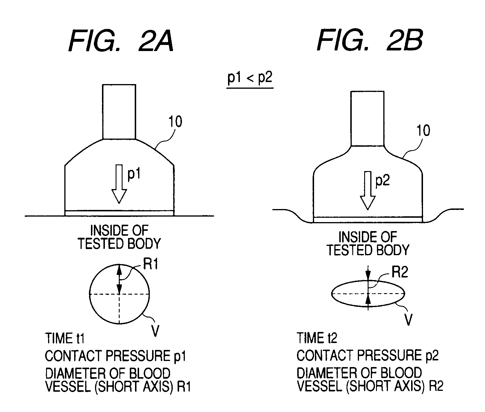
[0035]In a first embodiment, a pressure index value refers to a contact pressure between a probe and a tested body, which is caused by pressing the tested body with the probe.

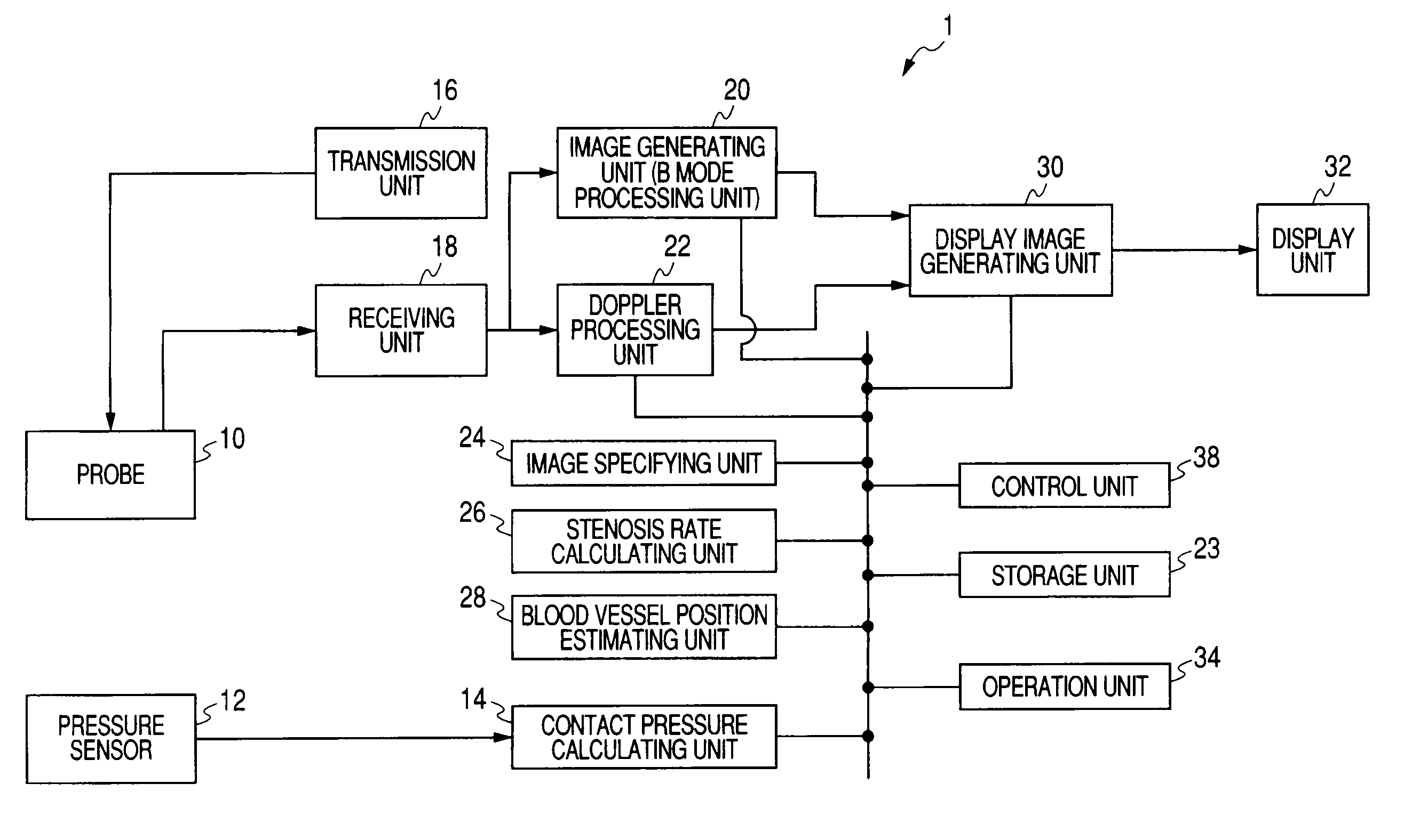
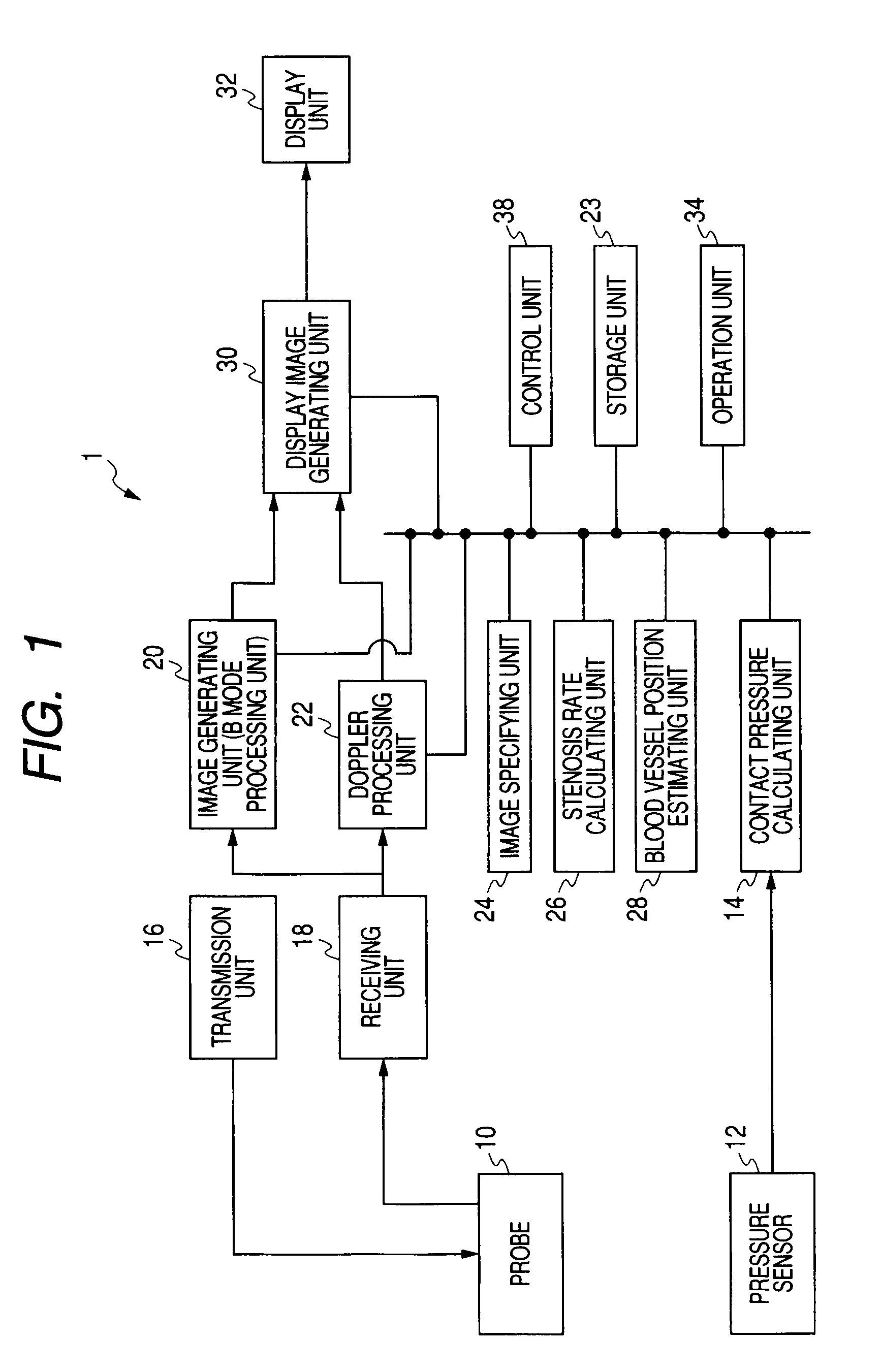
[0036]FIG. 1 is a view illustrating the configuration of an ultrasonic diagnostic apparatus 1 according to the first embodiment. As shown in the FIG. 1, the ultrasonic diagnostic apparatus 1 includes a probe 10, a pressure sensor 12, a contact pressure calculating unit 14, a transmission unit 16, a receiving unit 18, an image generating unit (B-mode processing unit) 20, a Doppler processing unit 22, a storage unit 23, an image specifying unit 24, a stenosis rate calculating unit 26, a blood vessel position estimating unit 28, a display image generating unit 30, a display unit 32, an operation unit 34, and a control unit 38. Hereinafter, each of the constituent components will be described.

[0037]The probe 10 has a vibrator array in which a plurality of vibrators for converting electric signals into ultrasonic wa...

second embodiment

[0106]In a second embodiment, a pressure index value is a Doppler shift frequency changing according to the movement of a blood vessel or a change of a blood flow that is caused by pressing a tested body with the probe 10. Moreover, in the following description, a component having approximately the same function as in the first embodiment is denoted by the same reference numeral, and repeat of explanation will only be made as needed.

[0107]FIG. 11 is a view illustrating the configuration of an ultrasonic diagnostic apparatus 50 according to a second embodiment of the invention. The ultrasonic diagnostic apparatus 50 includes a probe 10, a transmission unit 16, a receiving unit 18, an image generating unit (B-mode processing unit) 20, a Doppler shift frequency calculating unit (Doppler processing unit) 52, a storage unit 53, an image specifying unit 54, a stenosis rate calculating unit 26, a blood vessel position estimating unit 28, a display image generating unit 30, a display unit 3...

modified examples

[0142]In the first and second embodiments, examples using an ultrasonic image (B-mode image) on a two-dimensional tomographic plane have been explained. However, the invention does not need to be limited thereto but may also be applied to an ultrasonic image generated from volume data that is three-dimensional data. The ultrasonic image generated from volume data is assumed to be called a 3D image. In description of the following modified examples, a pressure index value is assumed to be a contact pressure in the same manner as in the first embodiment. However, in the modified examples, the pressure index value may also be a Doppler shift frequency.

[0143]The ultrasonic diagnostic apparatus 1 in the modified example repeatedly scans a three-dimensional region of a tested body with an ultrasonic wave by using a probe 10′.

[0144]An image generating unit 20′ reconstructs volume data on the basis of brightness data from the probe 10′ and generates data of the 3D image related to a predete...


PUM


Abstract

A generation unit generates data of a plurality of images whose scan time is different on the basis of an output of the probe. A calculation unit calculates a plurality of index values related to pressure of the probe against the tested body on the basis of a physical quantity changing with the strength of the pressure. A specifying unit specifies a first image, which corresponds to a first index value of the plurality of calculated index values, and a second image, which corresponds to a second index value, among the plurality of generated images. A display unit displays the specified first and second images side by side.

Description

CROSS-REFERENCE TO RELATED APPLICATIONS[0001]This application is based upon and claims the benefit of priority from prior Japanese Patent Application No. 2007-116123, filed Apr. 25, 2007, the entire contents of which are incorporated herein by reference.BACKGROUND OF THE INVENTION[0002]1. Field of the Invention[0003]The present invention relates to an ultrasonic diagnostic apparatus that scans a tested body pressed by a probe and an image display method thereof.[0004]2. Description of the Related Art[0005]In recent years, a diagnosis (hereinafter, referred to as a blood vessel echo) of a blood vessel using an ultrasonic wave is being widely performed. In the blood vessel echo, the existence of an intravascular thrombus or vascular stenosis and occlusion are diagnosed for various parts, such as a carotid artery, a main artery, a coronary artery, a peripheral artery, and a peripheral vein.[0006]There is a deep vein thrombosis (hereinafter, referred to as a ‘DVT’) as a disease related ...

Claims


Application Information

Patent Timeline
Patent Type & Authority Applications(United States)
IPC IPC(8): A61B8/00
CPCA61B5/6844A61B5/6886A61B8/06A61B8/13A61B8/42
Inventor NAKAYA, SHIGEMITSU
Owner TOSHIBA MEDICAL SYST CORP
Why Eureka
Try Eureka