Telescopic Rail Carriage Assembly for Suspending a Patient Lift

a technology for telescopic rails and carriages, which is applied in the direction of railway tracks, cranes, medical science, etc., can solve the problems of less suitable for carrying heavy loads and unsatisfactory rail construction

Inactive Publication Date: 2008-11-06
ERGOLET
View PDF3 Cites 15 Cited by
  • Summary
  • Abstract
  • Description
  • Claims
  • Application Information

AI Technical Summary

Benefits of technology

[0008]The telescopic rail and carriage assembly may comprise two inner sections coupled by an outer section. Thus, the span of the telescopic rail can be increased.
[0009]Preferably, the distance between the first support surfaces and the second support surfaces is substantially equal to the distance between the underside of the lower wheels and the underside of the upper wheels. Thus, a smooth transition of the carriage between the first and second support surfaces is possible.
[0012]Thus, a versatile support structure is provided that can be set up quickly in a room without the need for any contact with the walls or ceiling of the room.
[0013]The stabilizing ground support can be a bar extending transversely to the telescopic rail in two opposite directions from the upstanding pole components, preferably at its ends provided with castors or the like. Thus, it is easy to set up the upstanding pole components. With the castors it is easy to move the support structure.
[0017]Thus, an easy to adjust, set up an knock down support structure is provided that gives the patient lift two degrees of freedom in the horizontal plane.
[0019]The support structure can further be provided with two telescopic stabilizing rods extending between the opposite upper corners of the pairs of upstanding pole components connected by the respective telescopic rails to improve the rigidity of the structure.

Problems solved by technology

The rail construction is though not particularly stable, and therefore, less suitable for carrying heavy loads.

Method used


Image

  • Telescopic Rail Carriage Assembly for Suspending a Patient Lift
  • Telescopic Rail Carriage Assembly for Suspending a Patient Lift
  • Telescopic Rail Carriage Assembly for Suspending a Patient Lift

Examples


Embodiment Construction

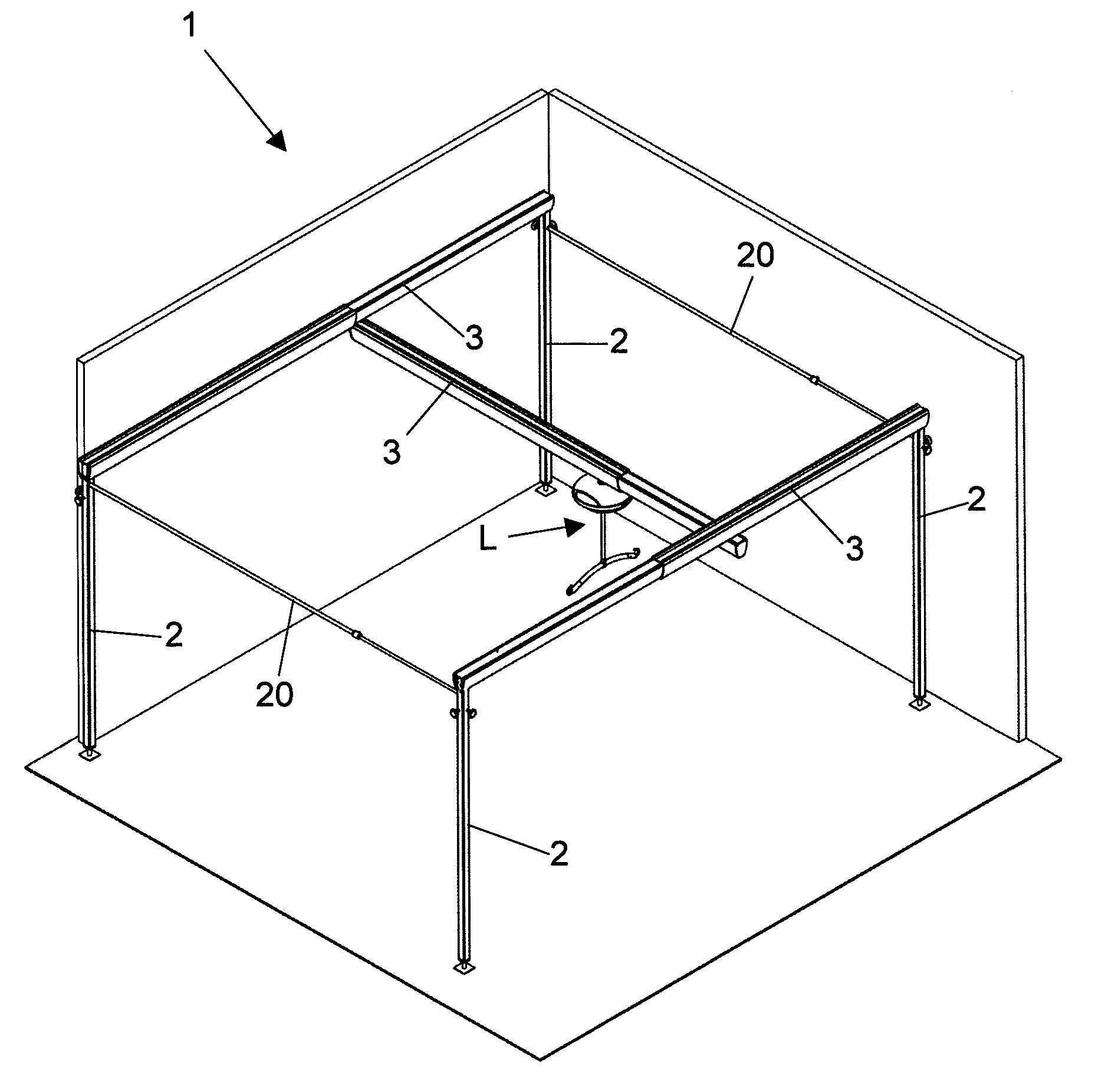
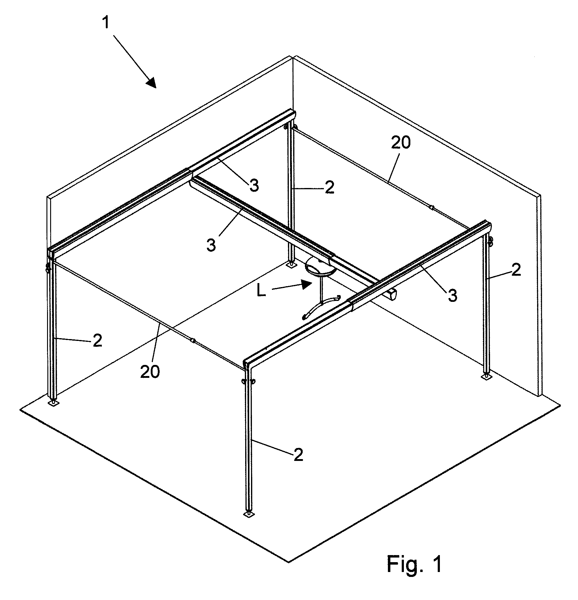
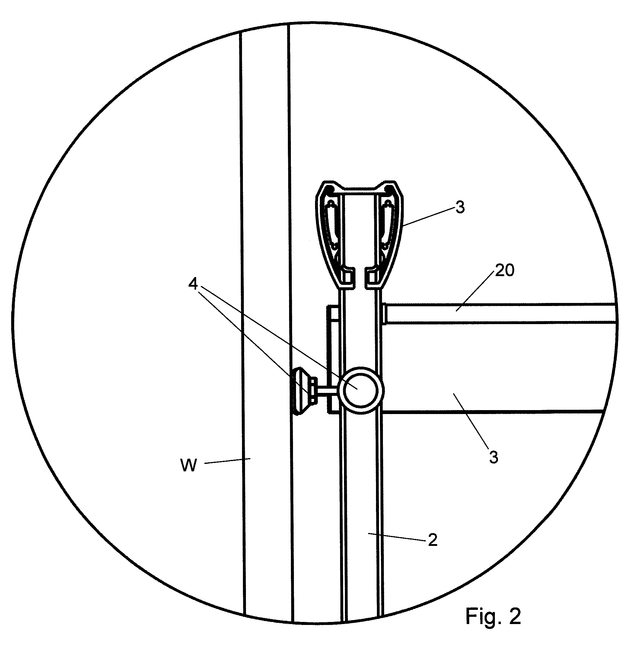
[0029]FIG. 1 illustrates a preferred embodiment of a support structure. The support structure 1 comprises two pairs of upstanding poles 2 of variable length. The top of the poles of each pair are connected to the opposite ends of a telescopic rail 3, also of variable length. The opposite ends of a third telescopic rail 3 are connected to the carriages in the other two telescopic rails 3. A patient lift L with or without a winch is suspended from the carriage in the third telescopic rail. Two telescopic stabilizing rods 20 extend between the corners where the telescopic rails 3 are connected to the upstanding poles 2. The stabilizing rods comprise an inner tube slidably received in an outer tube. The inner tube can be locked relative to the outer tube at a plurality of discrete positions by spring loaded locking pins (not shown) cooperating with corresponding openings the tubes. One end of the telescopic stabilizing rod is suited for fine adjustment in length by an end member (not sh...


PUM


Abstract

A telescopic rail and carriage assembly for suspending a patient lift. The carriage has a downward projection to which the patient lift is to be connected. The telescopic rail has an inner rail section and an outer rail section. The outer rail section is provided with first longitudinally extending interior support surfaces for supporting a lower set of wheels of the carriage. The inner rail section is provided with second longitudinally extending interior support surfaces for guiding and supporting an upper set of wheels of the carriage. In the extended state, the carriage is guided by the either the first or the second longitudinally extending support surfaces except where the first and second rail sections overlap. In the overlap, the wheels of the carriage are supported by both the first and second longitudinally extending interior support surfaces. A support structure for suspending a patient lift, having a telescopic rail provided with a carriage with means for attaching the patient lift thereto, a pair of upstanding pole components each provided with a stabilizing ground support. The opposite ends of the telescopic rail are connected to the upper ends of the upstanding pole components.

Description

[0001]This application is a continuation of U.S. application Ser. No. 10 / 555,494 filed Nov. 1, 2005, which claims priority to PCT / EP2004 / 005027 filed May 11, 2004, which claims priority to EP 030 10 894.8 filed May 15, 2003.FIELD OF THE INVENTION[0002]The present invention relates to a telescopic rail and carriage assembly for suspending a patient lift. Such telescopic rails are typically used as an overhead rail on a support structure or frame. A winch can be attached to the carriage and a lifting belt or the like can be suspended from the extendable cable or strap of the winch so as to be able to raise and lower a patient. The support structure itself may comprise two telescopic rails, whereby the telescopic rail that carries the patient lift is attached with its opposing ends to the respective carriages of the two telescopic rails of the support structure. Such support structures are particularly easy to be assembled, adjusted and disassembled again, thus allowing the installatio...

Claims


Application Information

Patent Timeline
Patent Type & Authority Applications(United States)
IPC IPC(8): A61G7/10E01B25/24
CPCA61G7/1015A61G7/1042A61G7/1061B66C7/10B66C9/06E01B25/24
Inventor HJORT, MOGENS
Owner ERGOLET
Why Eureka
Try Eureka