Connector terminal material, connector terminal, method for producing connector terminal and method for producing substrate with connector

Inactive Publication Date: 2005-01-20
AUTONETWORKS TECH LTD +2
View PDF11 Cites 8 Cited by
  • Summary
  • Abstract
  • Description
  • Claims
  • Application Information

AI Technical Summary

Benefits of technology

[0008] It is an object of the invention to provide a connector terminal material which can easily set a connector fixture and improve the yield of the product. It is

Problems solved by technology

And, in the worst case, there is a problem in that it is difficult to press-fit the termina

Method used


Image

  • Connector terminal material, connector terminal, method for producing connector terminal and method for producing substrate with connector
  • Connector terminal material, connector terminal, method for producing connector terminal and method for producing substrate with connector
  • Connector terminal material, connector terminal, method for producing connector terminal and method for producing substrate with connector

Examples


embodiment 1

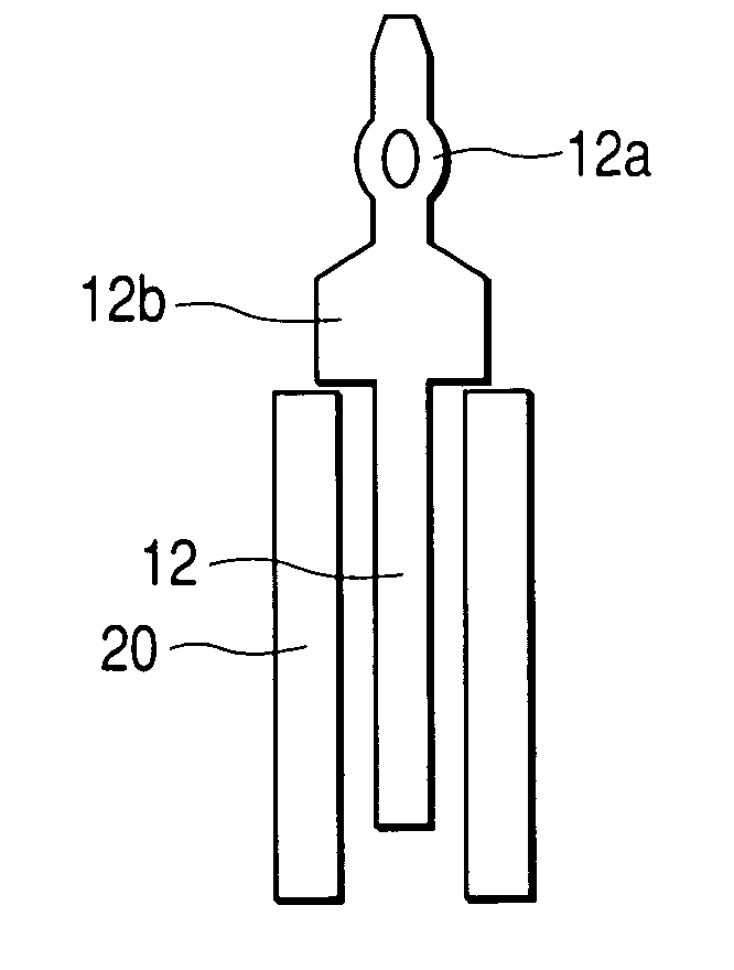
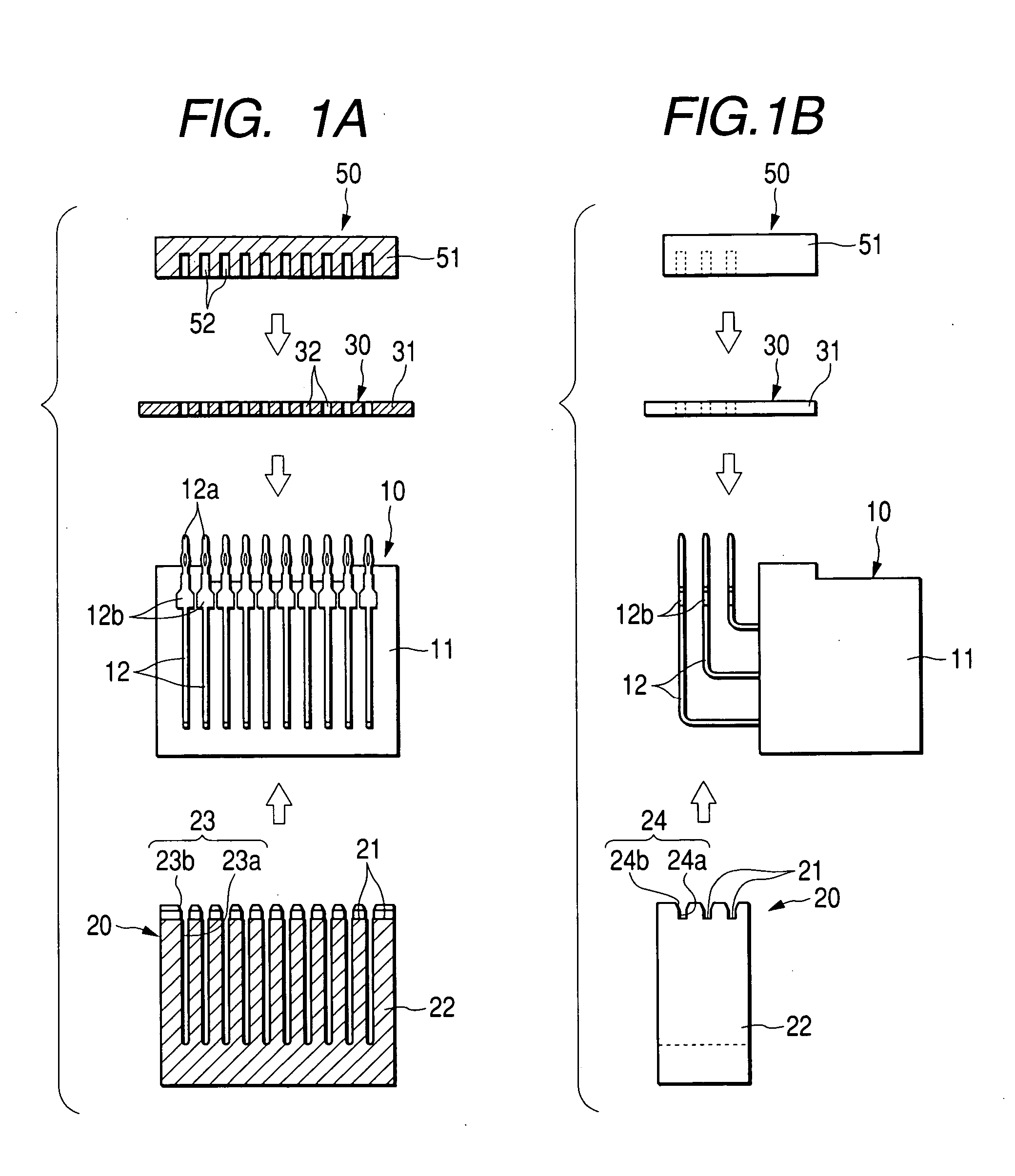
[0047]FIG. 1 is an illustration showing a state before a terminal of a press-fit connector of Embodiment 1 of the invention is press-fitted to a substrate. FIG. 1A is a front view including a section along a terminal array of a front side. FIG. 1B is a side view.

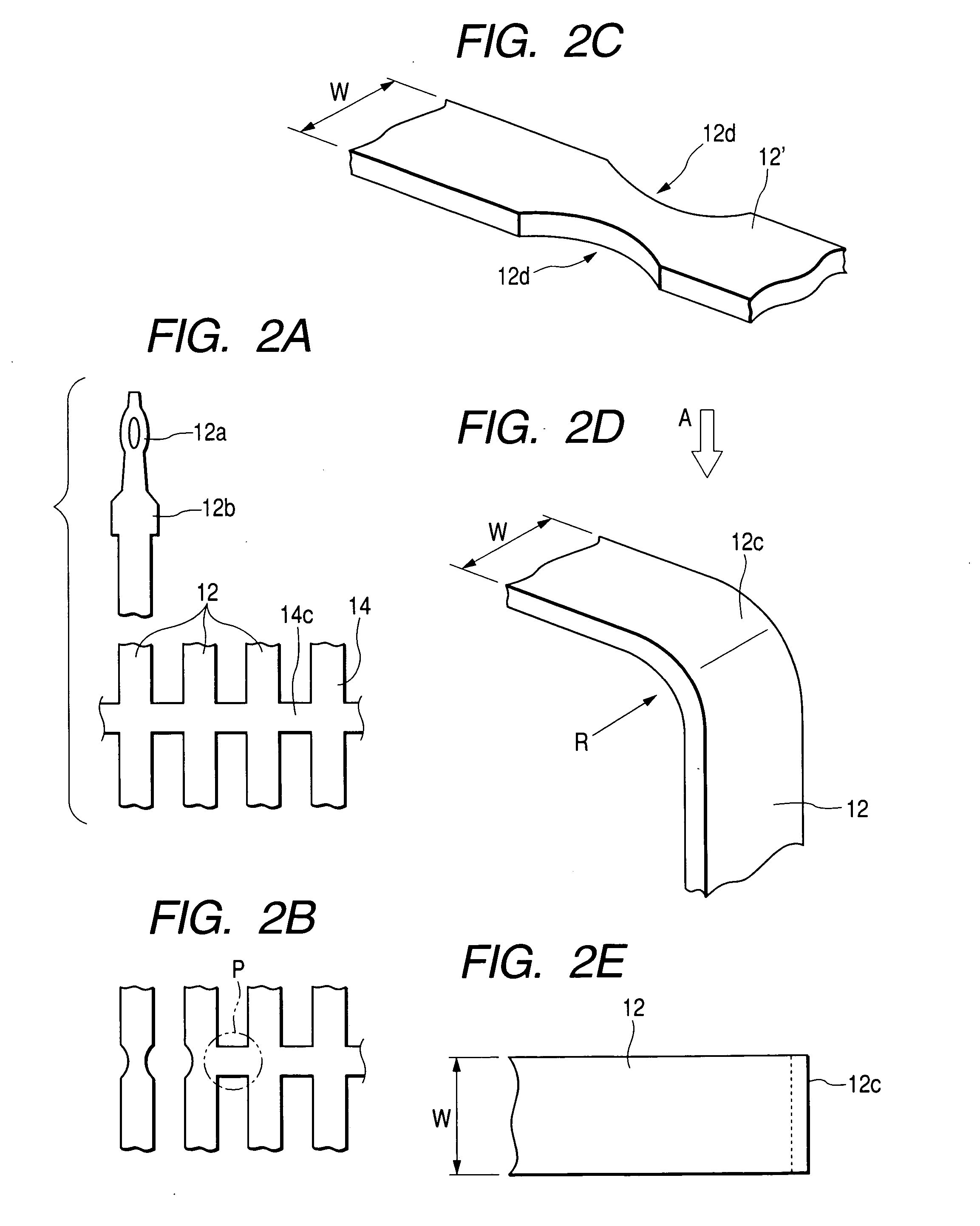
[0048]FIG. 2 is a view showing a state before and after bending a terminal according to Embodiment 1, wherein 2A is a plan view showing a shape example of a plate material to be punched out to mold a connector terminal plate, 2B is a plan view showing a punching process with respect to the plate material, 2C is a partial perspective view showing a state before bending the terminal, 2D is a partial perspective view showing a state after the bending is finished, and 2E is a plan view showing the terminal shown in FIG. 2D.

[0049]FIG. 3 is an illustration showing a state of setting the terminal of Embodiment 1 to a fixture. Void arrow marks shown in FIG. 1A, 1B show the mounting direction of each part at the time of press-fitti...

embodiment 2

[0071]FIG. 4 is an illustration showing a state before a terminal of a press-fit connector of Embodiment 2 of the invention is press-fitted to a substrate. FIG. 4A is a front view including a section along a terminal array of a front side. FIG. 4B is a sideview. FIG. 5 is an illustration showing a state of setting the terminal of Embodiment 2 to a fixture. Hereinafter, an explanation of elements which are common to Embodiment 1 is omitted.

[0072] As shown in FIG. 4, the bent part (bending part) 12c of the terminal body of the terminal 12 of Embodiment 2 swells in the specified direction crossing at right angles of the bending direction by bending the intermediate part in the longitudinal direction.

[0073] As shown in FIG. 5, the bent portion 12 forms the swelling portion by swelling in a direction of the terminal width crossing the at right angles bending direction.

[0074] A flange part 12b swelling in the above-described terminal width direction is formed at this side (inner side) ...


PUM


Abstract

A connector terminal material which extends in one direction and of which an intermediate specified part is bent is molded. The above-described specified part of the connector terminal material has notched parts formed at both sides in the terminal width direction and is made narrow thereat, and a flange part 12b is formed at this side of the tip end part. A connector terminal is produced by bending the specified part of the connector terminal material. While the connector terminal is being guided by a connector fixture which is narrower than the above-described flange part and has a wider deep groove than the other parts, the flange part is pressed by the press-fit surface of the end edge part of open end of the deep groove 23, whereby the tip end of the above-described connector terminal is press-fitted into the penetrating hole of the printed circuit board. Through the above-described processes, it is possible to produce a substrate with a connector.

Description

BACKGROUND OF THE INVENTION [0001] 1. Field of the Invention [0002] The invention relates to a connector terminal material used for a press-fit connector, a connector terminal, a method for producing a connector terminal, and a method for producing a substrate with a connector. [0003] 2. Description of the Related Art [0004] FIGS. 6 are illustrations showing one example of a state before a terminal of a conventional press-fit connector is press-fitted to a substrate. FIG. 6A is a front view including a section along a terminal array of a front side. FIG. 6B is a side view. Void arrow marks shown in FIG. 6 show the mounting direction of each part at the time of press fitting. Conventionally, a so-called press-fit connector is widely used as a connector which can be simply connected by press-fitting a terminal to a substrate without soldering. For instance, a method of press-fitting the terminal shown in FIGS. 6 is known. In this method, the flange part 512b of each terminal 512 is pu...

Claims


Application Information

Patent Timeline
IPC IPC(8): H01R13/04H01R12/58H01R12/71H01R43/16H01R43/20
CPCH01R12/585H01R12/712Y10S439/943H01R43/16
Inventor SAKATA, TOMOYUKISHIODA, RYOUSUKETAKATA, KENSAKU
Owner AUTONETWORKS TECH LTD
Why Eureka
Try Eureka