
Coordinate measuring method and device

Active Publication Date: 2008-11-06
HEXAGON TECH CENT GMBH
View PDF12 Cites 95 Cited by
  • Summary
  • Abstract
  • Description
  • Claims
  • Application Information

AI Technical Summary

Problems solved by technology

Such measures however bring also negative effects in that they increase bulk, mass, and cost of the system, while long and complex calibrations may reduce ease of use.
In many cases, ultimate precision can not be delivered if the measuring span of the machine is large, or if high-speed movement of the probe are needed, and a compromise has to be found between these opposing characteristics.
While industrial robots are versatile and fast, they do not exhibit, as a rule, the precision requested from metrology equipments.

Method used


Image

  • Coordinate measuring method and device
  • Coordinate measuring method and device
  • Coordinate measuring method and device

Examples


Embodiment Construction

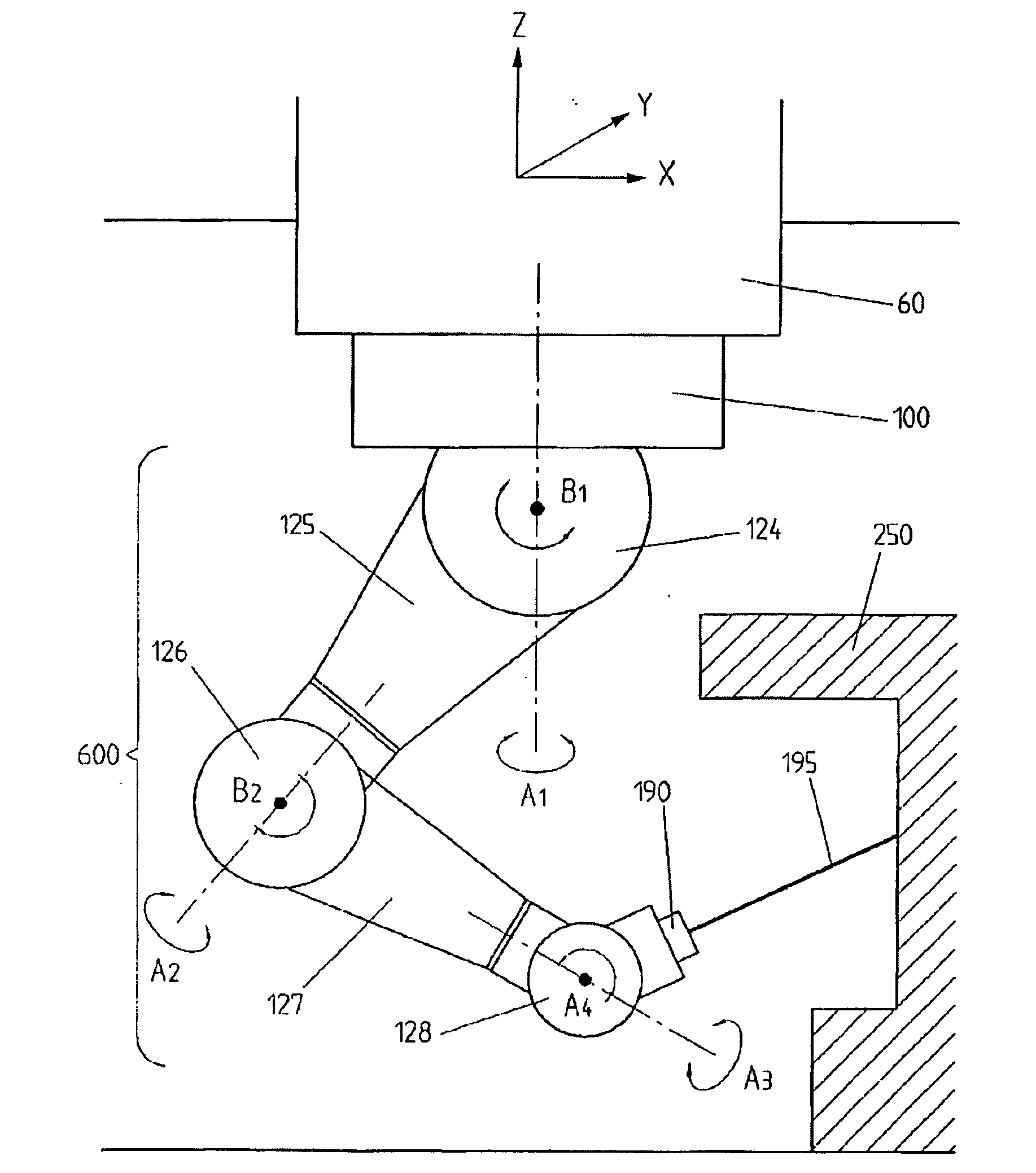
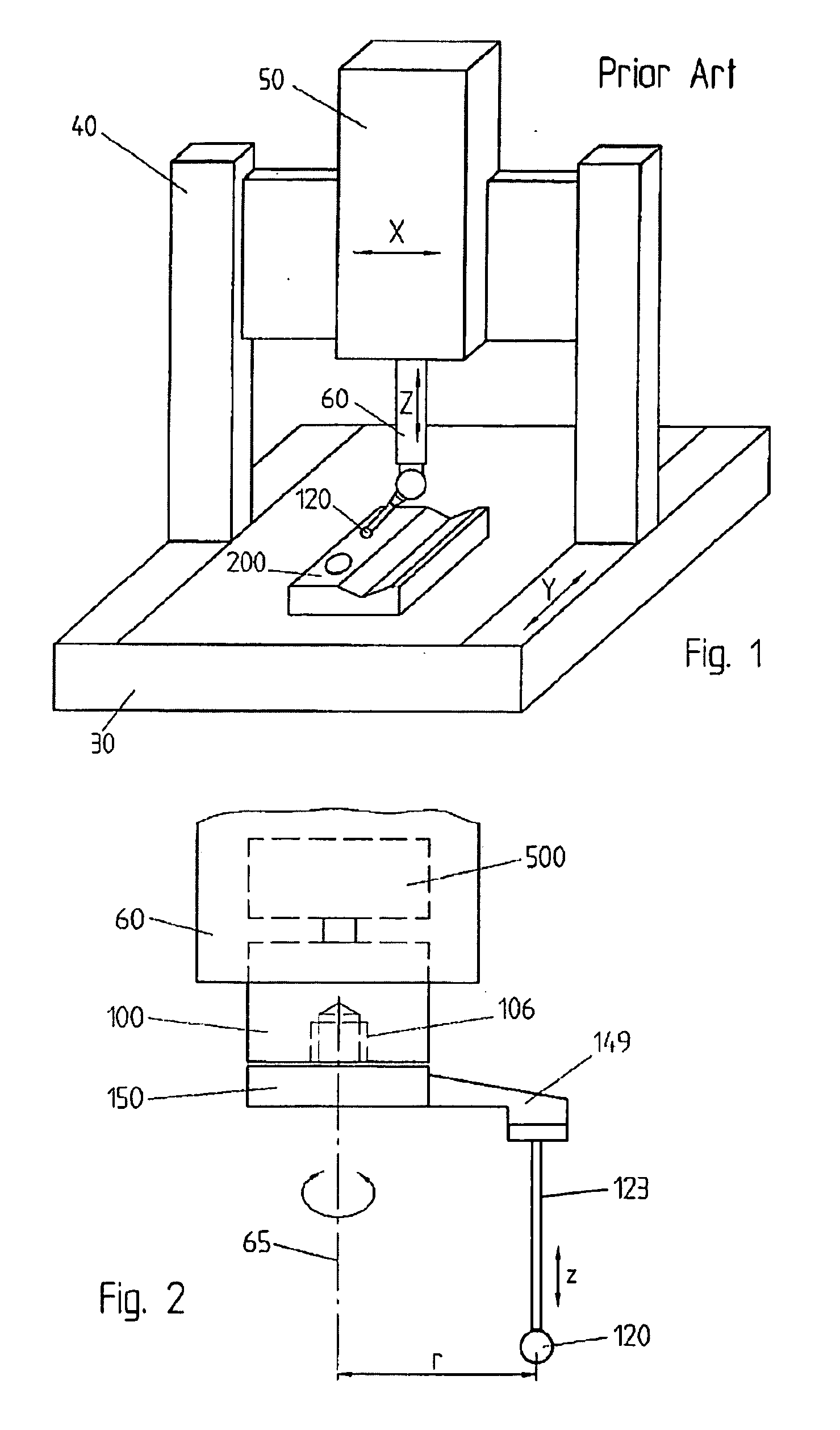
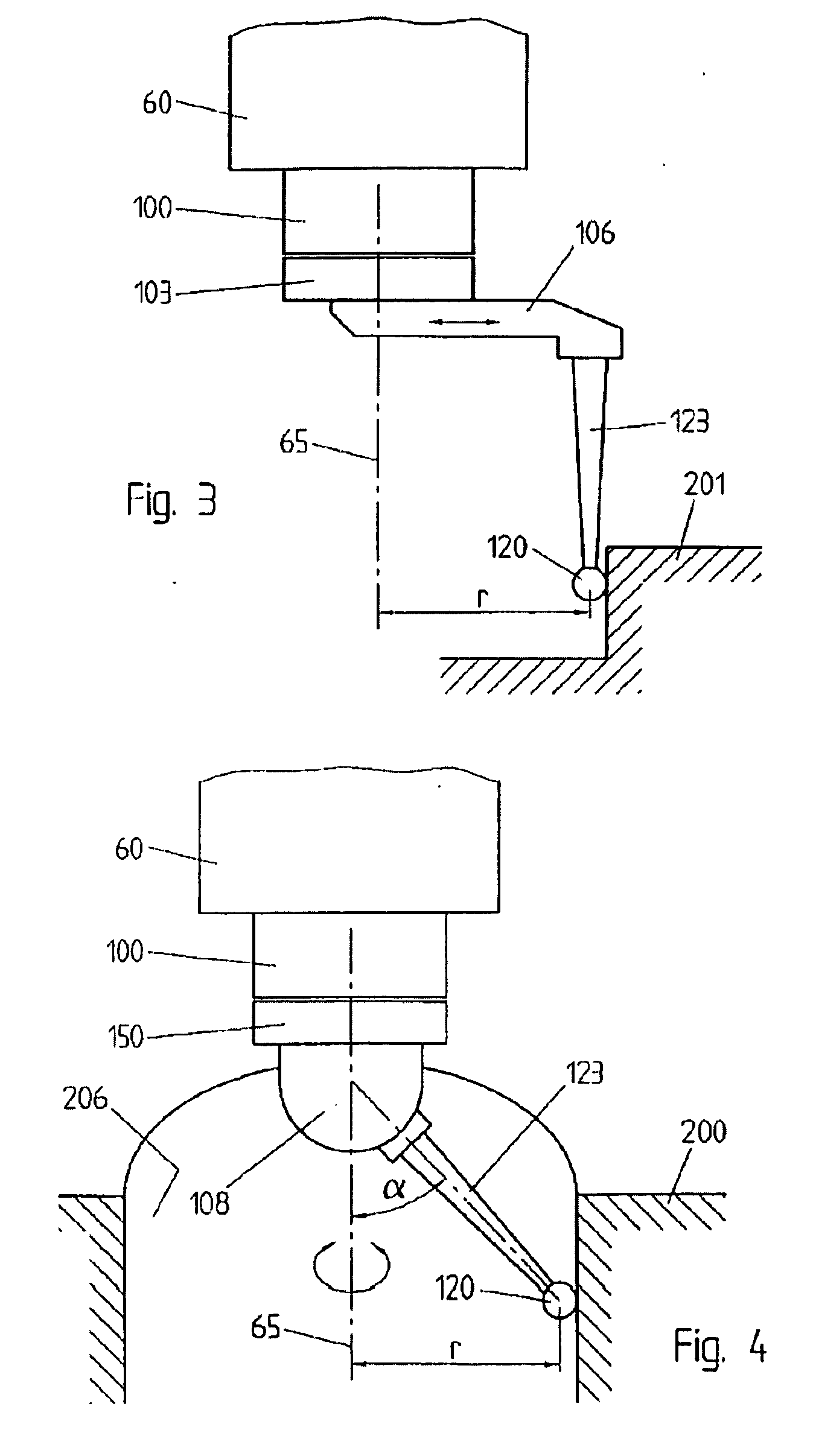
[0025]According to a first aspect of the invention, represented in FIG. 2, the measurement involves a contact probe 150 carrying a calibrated ball 120 at the tip of a stylus 123. The contact probe is attached in an offset position to a rotor 100, which is connected to a positioning platform 60, which could be for example a spindle of a coordinate measuring machine but also, in variant methods, a distal end of a robotized arm of an industrial robot, or a tool-holder in a numerically controlled machine tool, or any other suitable positioning apparatus, capable to position the rotor 100 in a desired position in space, in relation with a workpiece.

[0026]The rotor 100 can be rotated around the rotation axis 65 by an appropriate actuator, for example an electric motor 500, either in the positioning device 60 as represented or, in a non-represented equivalent variant, in the rotor itself. The angle of rotation of the rotor100 is encoded by an optical angle transducer, or by any other appro...


PUM


Abstract

A measuring method and system involving a measuring coordinate probe, which can be moved precisely, by appropriate actuators, with respect to a positioning platform (60) on which the probe is mounted; and whose position relative capable to said positioning platform (60) can be measured, by suitable encoders (780). The invention can be carried out with probes, actuators and encoders of different nature. The actuators (730) preferably allow the motion of the probe according to two or more independent degrees of freedom, so that the probe itself can be moved in a plane, or in a three-dimensional region of space, and its orientation can be chosen, within some suitable limits. The method and system of the invention provide very exact local measurement, even if the platform (60) does not deliver the very best precision

Description

REFERENCE DATA[0001]The present application claims priority from European Patent Application EP07107540, filed on May 4, 2007, in the name of the same applicant.FIELD OF THE INVENTION[0002]The subject technology relates generally with coordinate measuring methods and in particular, but not exclusively, with coordinate measuring machines and with their methods of use. These are devices for dimensional measuring are used to measure coordinates of points on the surface of mechanical elements, by means of an appropriate measuring probe. The measuring probe that may be of contact type, for example a touch probe, or non-contact type, like an optical probe or a laser probe. The scope of the present invention is not, however, limited to this particular class of devices.DESCRIPTION OF RELATED ART[0003]Coordinate positioning machines, also indicate as coordinate measuring machines, or CMM, generally comprise a fixed reference surface, for example a massive granite table chosen for its high ri...

Claims


Application Information

Patent Timeline
IPC IPC(8): G01B5/008
CPCG01B5/008G01B21/047
Inventor JORDIL, PASCALPETTERSSON, BO
Owner HEXAGON TECH CENT GMBH
Learn More