Electrical switching apparatus, and yoke assembly and spring assembly therefor

Active Publication Date: 2008-11-06
EATON INTELLIGENT POWER LIMITED
View PDF8 Cites 2 Cited by
  • Summary
  • Abstract
  • Description
  • Claims
  • Application Information

AI Technical Summary

Benefits of technology

[0044]Referring again to FIGS. 2A and 2B, another advantage of the disclosed yoke assembly 100, will now be discussed. Specifically, the circuit breaker 2 (FIG. 1) may further include one or both of an indicator 300 (shown in block form in FIG. 2A), as defined herein, and an interlock 400 (shown in block form in FIG. 2B), as defined herein. At least one of the first and second sides 106,108 of the yoke assembly 100 is structured to be coupled directly to the corresponding indicator 300 (see, for example, second side 108 of the yoke assembly 100 coupled to indicator 300 in FIG. 2A) and the interlock 400 (see, for example, first side 106 coupled directly to interlock 400 in FIG. 2B). Accordingly, it will be appreciated, that as the first and second sides 106,108 of the yoke assembly 100 translate back and forth (see, for example, first side 106, which translates left and right with respect to FIGS. 3A and 3B), they provide a reference point from which to directly transfer information concerning the position and, therefore, the status of the circuit breaker 2 (FIG. 1). More specifically, features of the circuit breaker 2 (FIG. 1) such as, for example and without limitation, the aforementioned indicator 300 (FIG. 2A) and interlock 400 (FIG. 2B) can be directly coupled to the first and / or second side(s) 106,108 of the yoke assembly 100, without a plurality of separate linking elements, as defined herein. In this manner, when the yoke assembly 100 and, in particular, the sides 106,108 thereof, move, the yoke assembly 100 actuates the corresponding feature (e.g., without limitation, indicator 300 (FIG. 2A); interlock 400 (FIG. 2B)).

Problems solved by technology

These two objectives are somewhat contradictory, and are difficult to achieve because of the limited amount of space that is available within the circuit breaker.
It is, therefore, difficult to effectively arrange the spring assembly and / or related structures within the circuit breaker housing in a manner that affords the desired leverage and spring energy.
In this regard, known circuit breaker designs leave much to be desired.

Method used


Image

  • Electrical switching apparatus, and yoke assembly and spring assembly therefor
  • Electrical switching apparatus, and yoke assembly and spring assembly therefor
  • Electrical switching apparatus, and yoke assembly and spring assembly therefor

Examples


Embodiment Construction

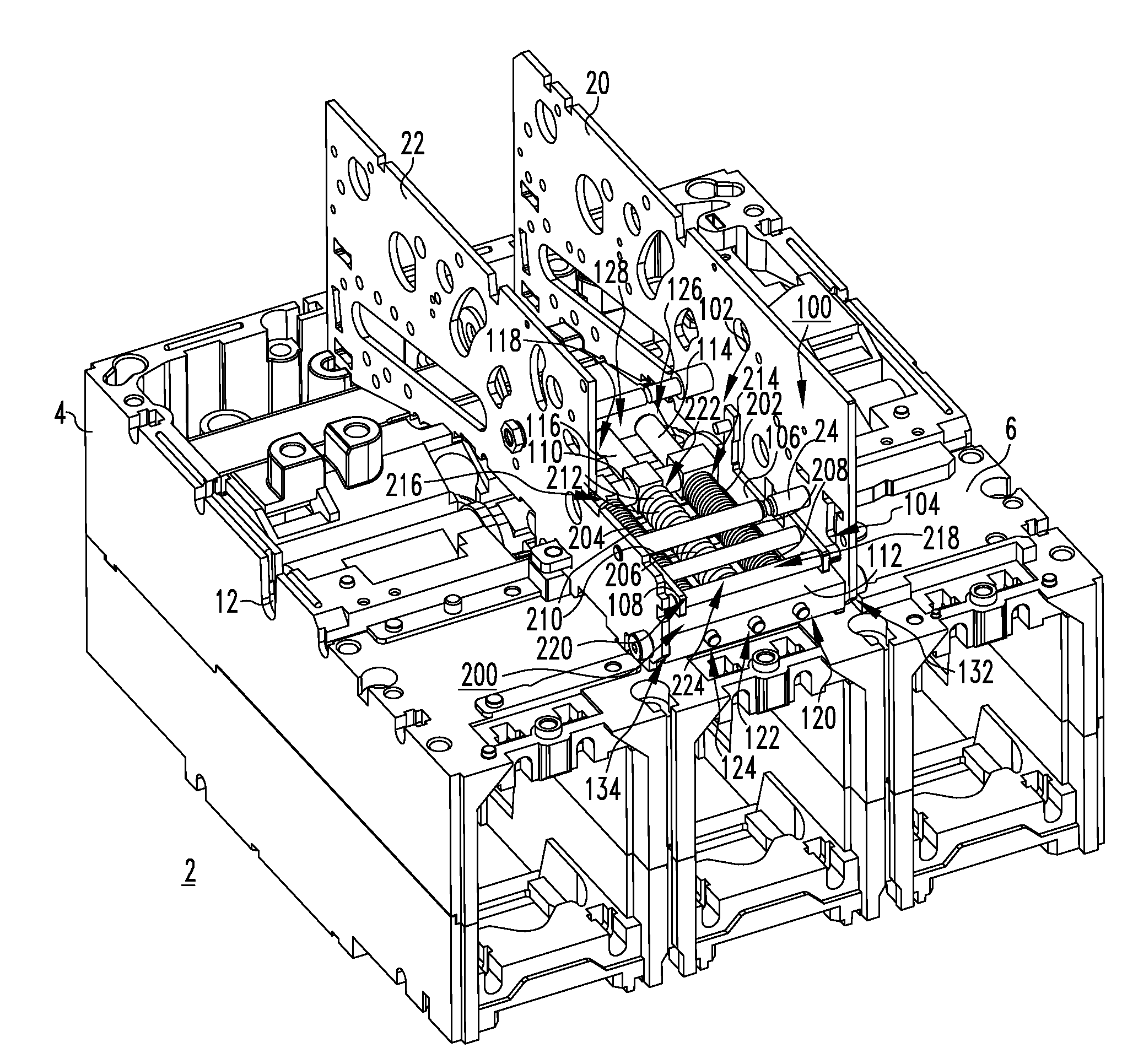
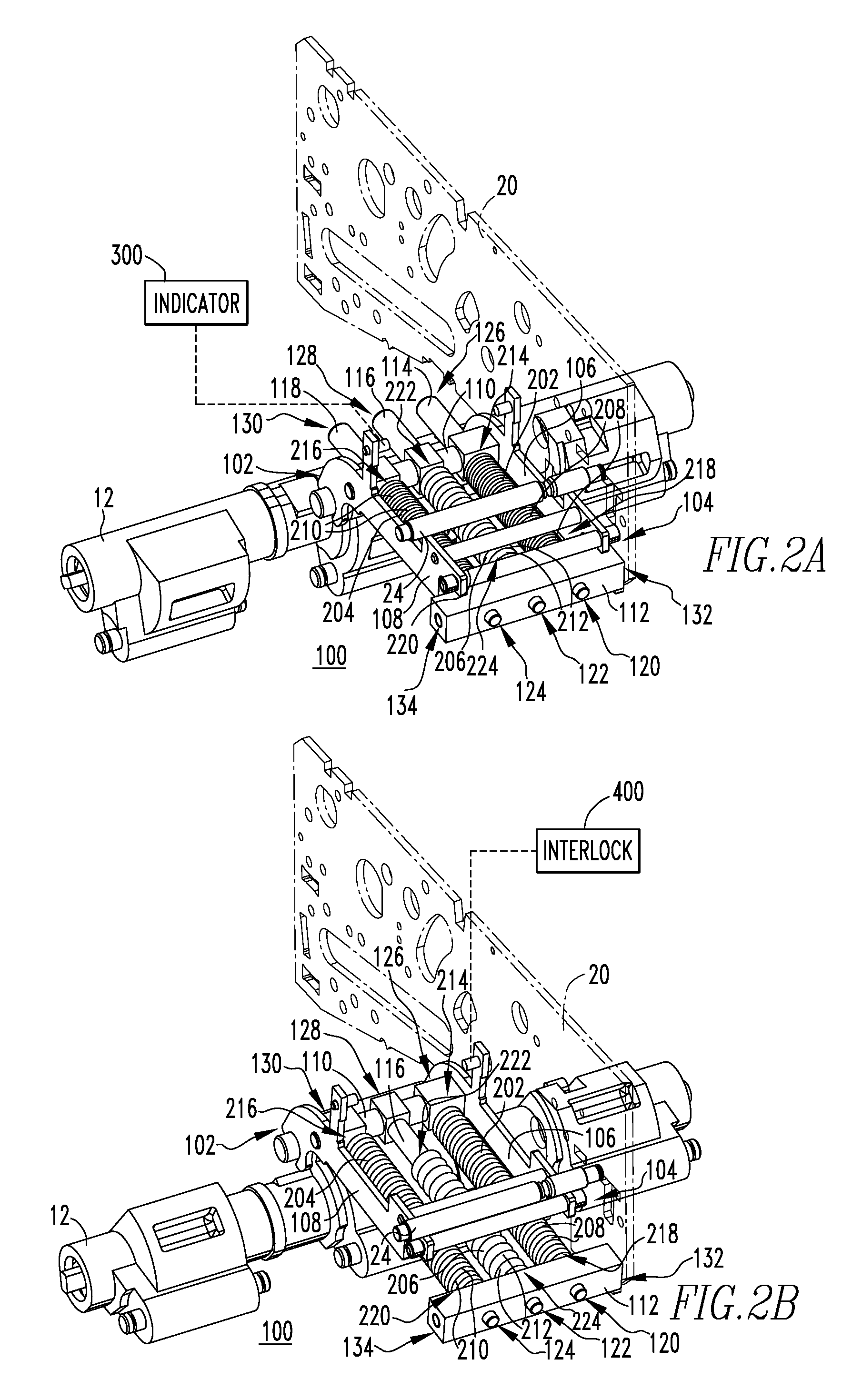
[0026]For purposes of illustration, embodiments of the invention will be described as applied to low-voltage circuit breakers, although it will become apparent that they could also be applied to a wide variety of electrical switching apparatus (e.g., without limitation, circuit switching devices and other circuit interrupters, such as contactors, motor starters, motor controllers and other load controllers) other than low-voltage circuit breakers and other than low-voltage electrical switching apparatus.

[0027]Directional phrases used herein, such as, for example, top, bottom, upper, lower, front, back, clockwise, counterclockwise and derivatives thereof, relate to the orientation of the elements shown in the drawings and are not limiting upon the claims unless expressly recited therein.

[0028]As employed herein, the term “spring rate” refers to the amount of weight needed to compress a spring a certain distance. For example and without limitation, for linear springs, a spring which h...


PUM


Abstract

A spring assembly is provided for a yoke assembly of an electrical switching apparatus including a housing, separable contacts enclosed by the housing, and an operating mechanism structured to open and close the separable contacts. The operating mechanism includes a pole shaft. The yoke assembly is coupled to the pole shaft and is movable among first and second positions corresponding to the separable contacts being closed and open, respectively. The spring assembly includes a number of first springs having a first spring rate and being coupled to the yoke assembly, and a number of second springs having a second spring rate and being coupled to the yoke assembly. The second spring rate is different than the first spring rate. The number of first springs and the number of second springs bias the yoke assembly toward the second position.

Description

CROSS-REFERENCE TO RELATED APPLICATIONS[0001]This application is related to co-pending, commonly assigned:[0002]U.S. patent application Ser. No. 11 / 696,810, filed Apr. 5, 2007, and entitled “ELECTRICAL SWITCHING APPARATUS AND TRIP ACTUATOR ASSEMBLY THEREFOR”;[0003]U.S. patent application Ser. No. 11 / 696,815, filed Apr. 5, 2007, and entitled “ELECTRICAL SWITCHING APPARATUS, AND TRIP ACTUATOR ASSEMBLY AND RESET ASSEMBLY THEREFOR”; and[0004]U.S. patent application Ser. No. 11 / 696,812, filed Apr. 5, 2007, and entitled “ELECTRICAL SWITCHING APPARATUS AND TRIP ACTUATOR RESET ASSEMBLY THEREFOR”, which are hereby incorporated herein by reference.BACKGROUND OF THE INVENTION[0005]1. Field of the Invention[0006]The invention relates generally to electrical switching apparatus and, more particularly, to yoke assemblies for electrical switching apparatus, such as circuit breakers. The invention also relates to spring assemblies for circuit breaker yoke assemblies.[0007]2. Background Information[...

Claims


Application Information

Patent Timeline
IPC IPC(8): H01H5/06
CPCH01H3/3052H01H71/12
Inventor SPITSBERG, YURISLEPIAN, ROBERT M.GIBSON, PERRY R.PARKS, DAVID A.MARKS, DOUGLAS C.RAKUS, PAUL R.WEISTER, NATHAN J.WEHRLI, HENRY A.
Owner EATON INTELLIGENT POWER LIMITED
Why Eureka
Try Eureka