
Composite Carbon Fiber Bicycle Crank and Its Method of manufacture

a technology of composite carbon fiber and bicycle crank, which is applied in the direction of folding cycles, bicycle equipment, cycles, etc., can solve the problems of troublesome manufacturing of bicycle cranks b>92/b>

Inactive Publication Date: 2008-11-06
TSAI CARLOS
View PDF4 Cites 21 Cited by
  • Summary
  • Abstract
  • Description
  • Claims
  • Application Information

AI Technical Summary

Benefits of technology

[0010]It is an objective of the present invention to provide a method of manufacture for forming a robust and light weighted bicycle crank.
[0011]It is another objective of the present invention to provide a bicycle crank which is aesthetically pleasing.

Problems solved by technology

However, manufacturing the bicycle crank 92 is troublesome.

Method used


Image

  • Composite Carbon Fiber Bicycle Crank and Its Method of manufacture
  • Composite Carbon Fiber Bicycle Crank and Its Method of manufacture
  • Composite Carbon Fiber Bicycle Crank and Its Method of manufacture

Examples


Embodiment Construction

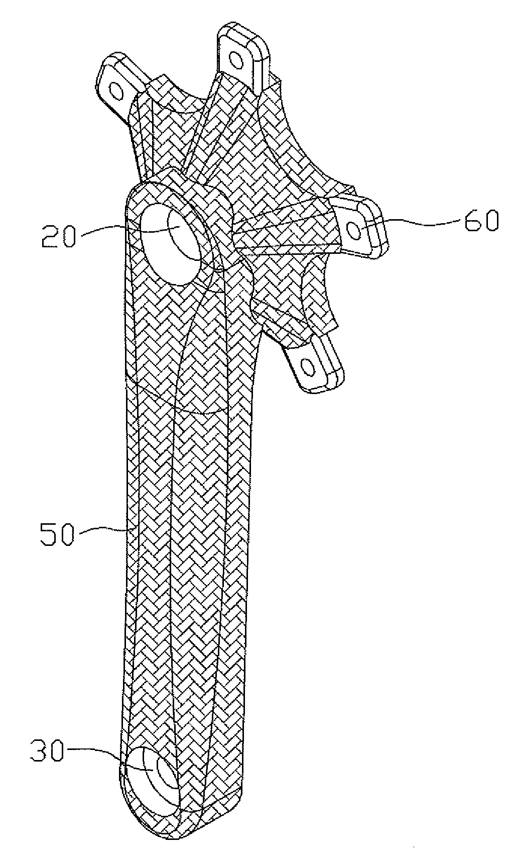
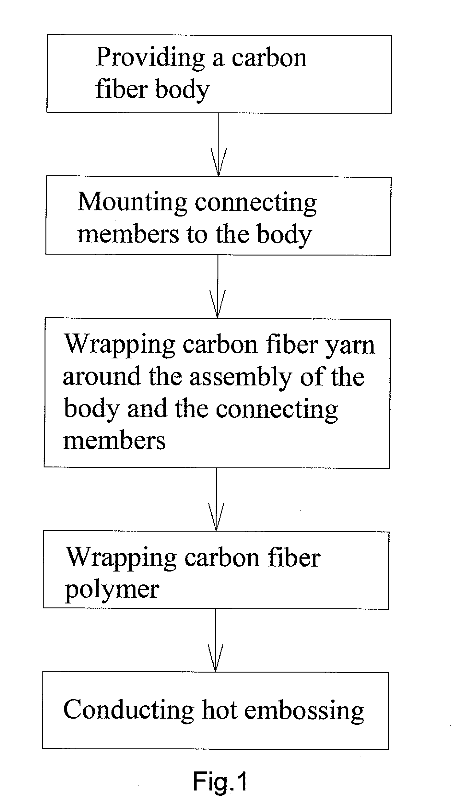
[0024]Referring to FIG. 1, there is shown a method of manufacture of a bicycle crank in accordance with the present invention. The method includes providing a body 10 made of carbon fiber, mounting a first connecting member 20 and a second connecting member 30 to the body 10, wrapping carbon fiber yarn 40 around the assembly of the body 10 and the first and second connecting members 20, 30, wrapping carbon fiber polymer 50, and conducting hot embossing.

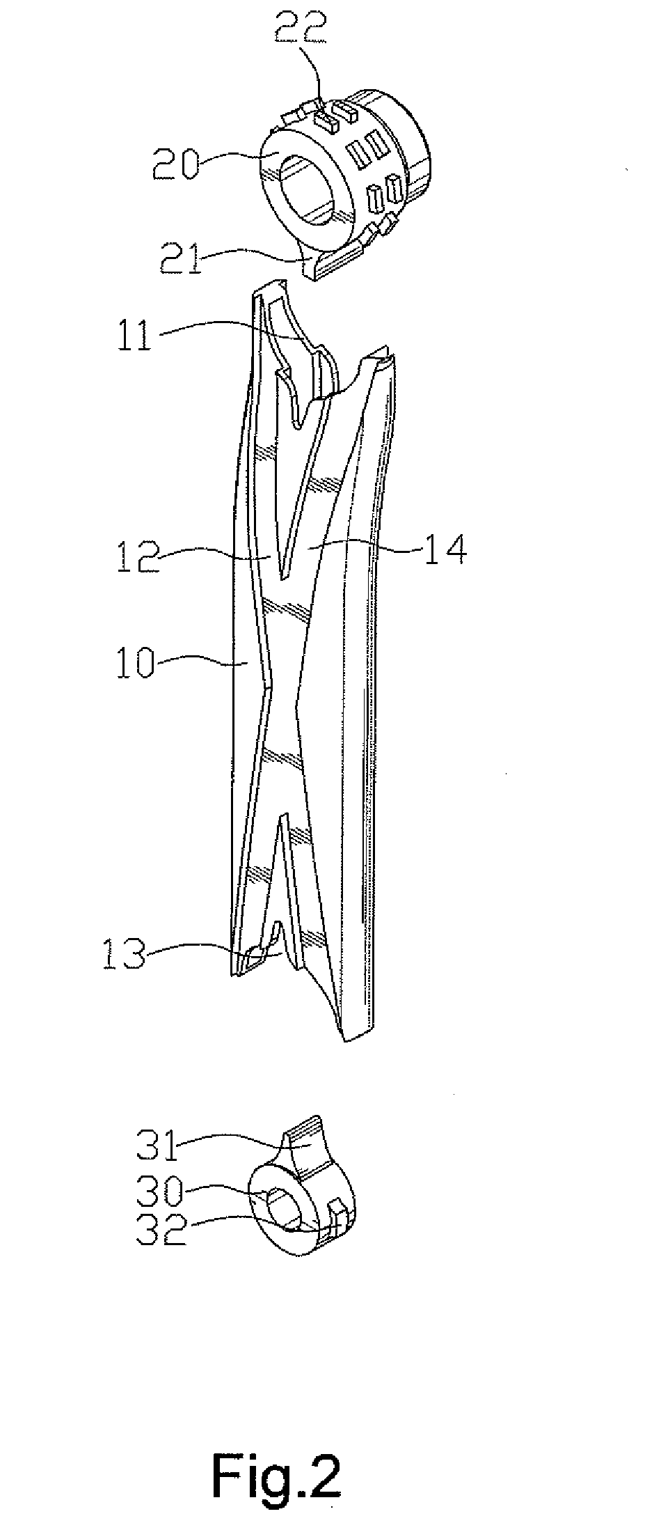
[0025]Referring to FIGS. 2 through 5, the body 10 is hollow and includes a first opening 11 at one end for receiving the first connecting member 20, a second opening 13 at another end for receiving the second connecting member 30. The body 10 also includes a first groove 12 and a second groove 14 recessed into the outer surface thereof, wherein the first and second grooves 12, 14 are intercrossed and both grooves extend from the first opening 11 to the second opening 13.

[0026]The first connecting member 20 and the second connecting me...


PUM

PropertyMeasurementUnit
Angleaaaaaaaaaa

Abstract

A method of manufacture of forming a composite carbon fiber bicycle crank includes providing a hollow carbon fiber body, with the body including a first opening at one end and the second opening at the other end, mounting a first connecting member and a second connecting member in the first opening and the second opening of the body respectively, wrapping carbon fiber yarn made up of carbon yarn around the assembly of the body and the first and second connecting members, wrapping carbon fiber polymer, and performing hot embossing.

Description

BACKGROUND OF THE INVENTION[0001]1. Field of the Invention[0002]The present invention relates to a bicycle crank and its method of manufacture, in particular, to a composite carbon fiber bicycle crank which copies the principle of how tendon connecting muscle with a bone and its method of manufacture.[0003]2. Description of the Related Art[0004]In order to build a lighter bicycle, compound steel and aluminum alloy have been utilized in place of metal for the manufacture of the bicycle cranks.[0005]Referring to FIG. 9, a conventional bicycle crank 90 made of aluminum includes a metal strip 901 having a first end and a second end, a first axle fastening member 902 and a second axle fastening member 903, with the first end adjacent to the first axle fastening member 902, and with the second end adjacent to the second axle fastening member 903. The metal strip 901, the first axle fastening member 902, and the second axle fastening member 903 are wrapped with a composite material 904.[00...

Claims


Application Information

Patent Timeline
IPC IPC(8): B21D53/88
CPCB62K19/16Y10T29/49622B62M3/00B29L2031/06B29C70/30B29K2705/00
Inventor TSAI, CARLOS
Owner TSAI CARLOS
Learn More