Magnetically activated switch assembly

a technology of magnetically activated switch and assembly, which is applied in the direction of optical elements, protective garments, instruments, etc., can solve the problems of less effective magnetically activated switch assembly and improper turning off of integrated night vision goggles, and achieve the effect of reducing the magnetic flux conducted

Active Publication Date: 2008-11-06
NOROTOS
View PDF10 Cites 196 Cited by
  • Summary
  • Abstract
  • Description
  • Claims
  • Application Information

AI Technical Summary

Benefits of technology

The technical effect of adding a shunt bar in an electrical device is to reduce interference between components caused by high levels of magnetic activity. This happens when certain parts of the device are placed in a specific way during use. By adding a shunt bar, it helps direct the flow of electricity away from areas where it may cause problems, resulting in better performance overall.

Problems solved by technology

The technical problem addressed in this patent is finding an improved magnetically activated switch assembly for helmet-mounted night vision goggles that can reliably activate at specific locations while preventing unwanted activation from external sources like magnetic interference or environmental factors. Additionally, it should allow the goggles to stay on in one position and turn them off in another without causing any issues during operation.

Method used


Image

  • Magnetically activated switch assembly
  • Magnetically activated switch assembly
  • Magnetically activated switch assembly

Examples


Embodiment Construction

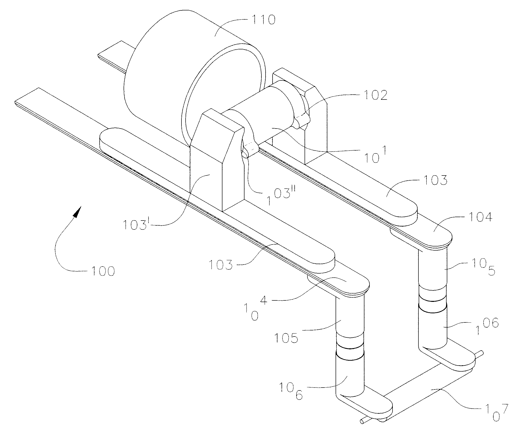
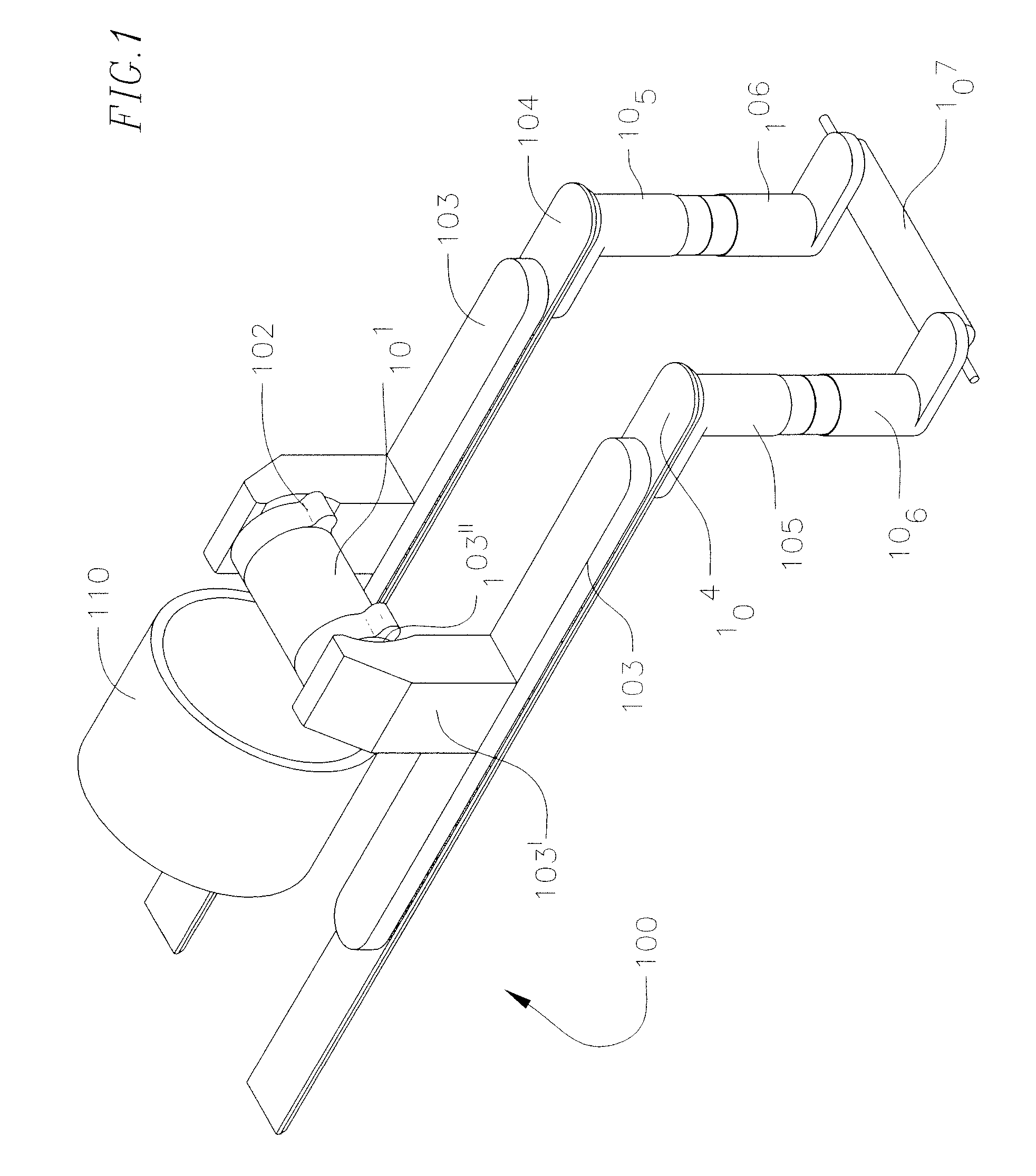
[0049]FIG. 1 is a perspective view of a magnetically activated switch assembly 100 according to an exemplary embodiment of the present invention. The magnetically activated switch assembly 100 includes a magnet 101 and may additionally include magnet shoes 102 positioned on the north and south poles of the magnet 101. Adjacent the magnet shoes 102 and separated by an air gap are vertical shoes 103. The vertical shoes 103 are positioned above monorail strip conductors 104 and each have a protruding arm 103′ that extends adjacent each pole of the magnet 101 to conduct the magnetic flux. The protruding arm 103′ may include an indentation 103′ when magnet shoes 102 are located on poles of the magnet 101. The monorail strip conductors 104 are T-shaped or dovetail shaped and fit into a channel on the bottom of a monorail 121 (FIG. 3) such that they are positioned above the upper transfer conductors 105, thus allowing the upper transfer conductors 105 to slide along bottom portions of the ...


PUM

PropertyMeasurementUnit
Angleaaaaaaaaaa
Angleaaaaaaaaaa
Magnetic permeabilityaaaaaaaaaa

Abstract

A magnetically activated switch assembly is provided. The magnetically activated switch assembly includes a magnet and a magnetic circuit. The magnetic circuit includes a magnetically activated switch, a first set of flux conductors, and a second set of flux conductors. The first set of flux conductors has first flux conductor flanges adapted to conduct flux from ends of the magnet. The second set of flux conductors is slidingly positioned relative to the first set of flux conductors and is adapted to conduct flux from the first set of flux conductors to the magnetically activated switch. The first set of flux conductors are adapted to rotate clockwise or counter-clockwise and to tilt up or down. The first magnetic circuit is adapted to conduct flux to activate the magnetically activated switch only when the first flux conductor flanges are rotationally aligned with ends of the magnet and tilted to an operational position.

Description


Claims


Application Information

Patent Timeline
Owner NOROTOS
Why Eureka
Try Eureka