Projector

a projector and projector technology, applied in the field of projectors, can solve the problems of further reducing the efficiency of heat dissipation and the disadvantage of the application of the structure shown by jp-um-a-1-65534 to the projector, and achieve the effect of efficient and effective cooling of the optical system

Inactive Publication Date: 2006-08-03
SEIKO EPSON CORP
View PDF5 Cites 43 Cited by
  • Summary
  • Abstract
  • Description
  • Claims
  • Application Information

AI Technical Summary

Benefits of technology

[0016] In the projector, it is made possible to cool the light source by connecting the light source, which launches light for image projection and generates the largest amount of heat among the optical elements constituting the optical system of the projector, with the tripod-fixing part. Therefore, the light source, which generates the largest amount of heat, is cooled and as such, the optical system can be cooled efficiently and effectively.

Problems solved by technology

However, the application of the structure shown by JP-UM-A-1-65534 to a projector poses a disadvantage as follows.
In addition, there is another disadvantage in that the efficiency of heat dissipation is further decreased when the structure is applied in the condition where the tripod-attachment part (with the tripod that the tripod-attachment part is fixing) is removed.

Method used


Image

  • Projector
  • Projector
  • Projector

Examples


first embodiment

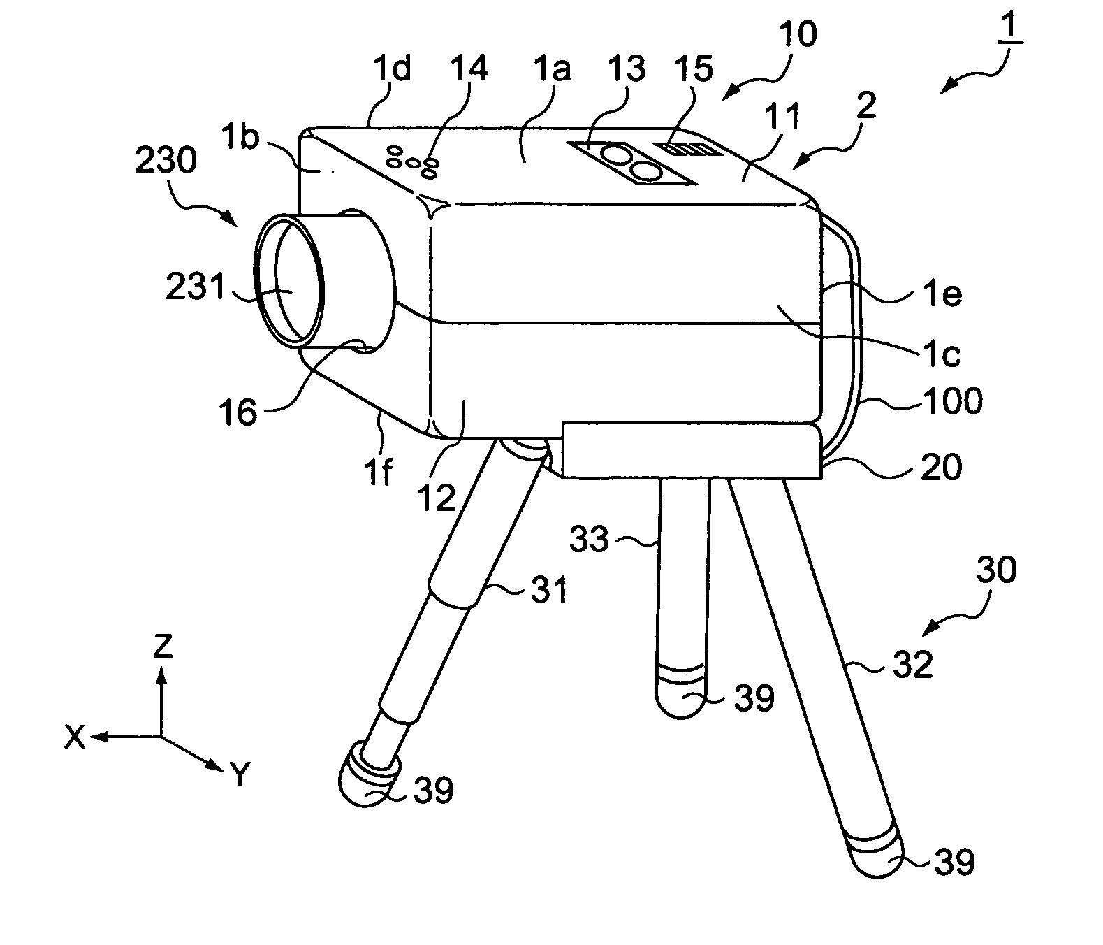
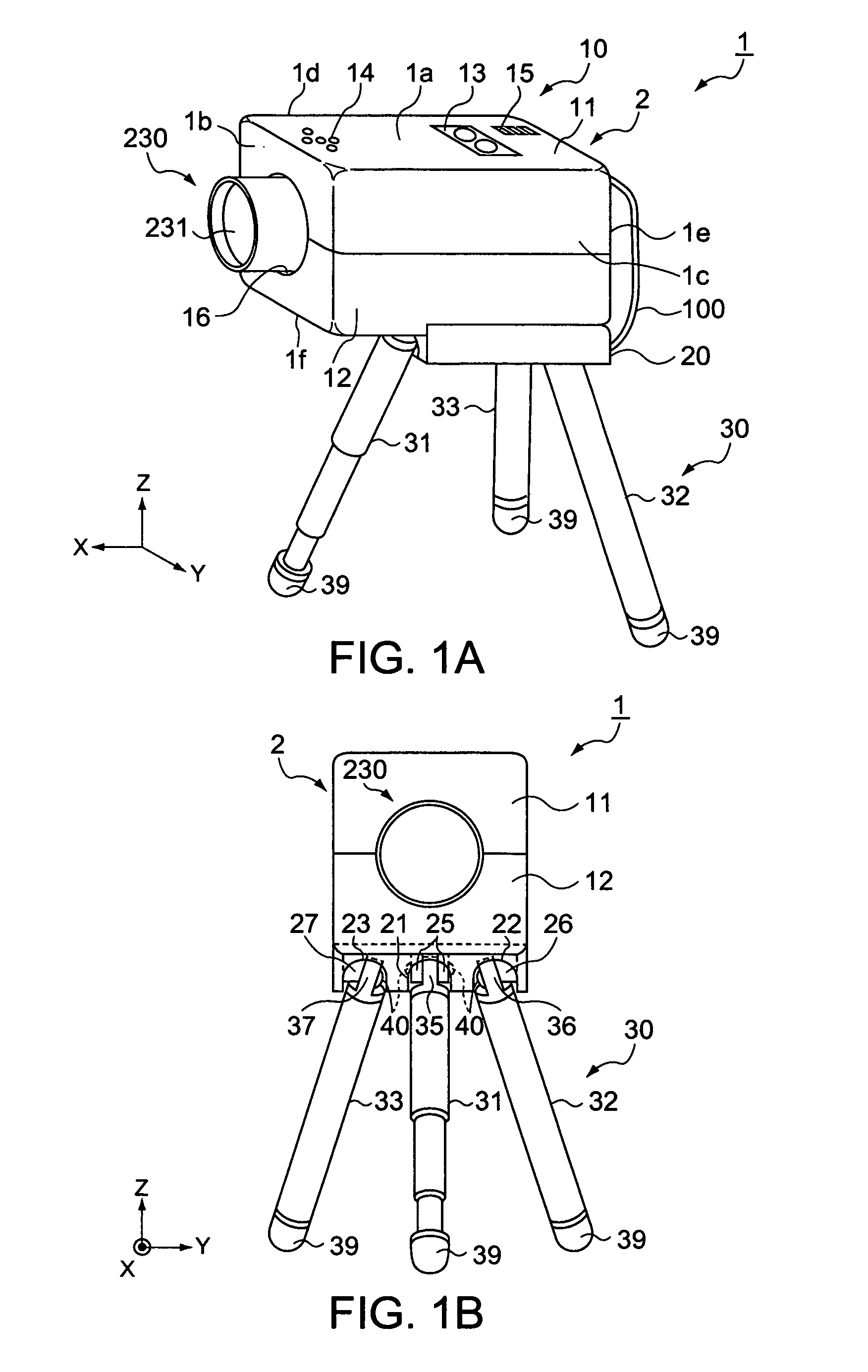
[0025]FIG. 1A is a general perspective view of a projector according to an embodiment of the invention with its tripod legs stretched wide apart, showing an external appearance of the projector. FIG. 1B is a front view of the projector with the tripod legs stretched wide apart. With reference to FIGS. 1A, 1B, the configuration of the projector 1 will be described based on the external appearance.

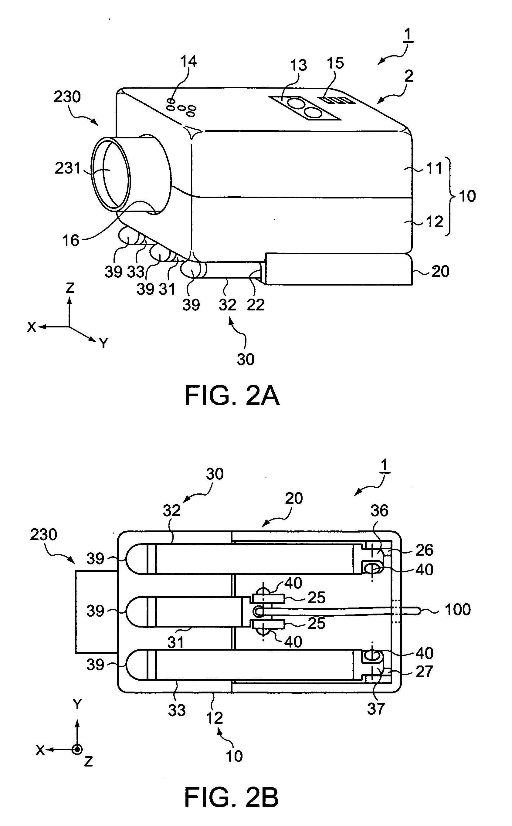
[0026] For convenience of description of the configuration, the six exposed faces of the main body 2 of the projector 1 are identified as a top face 1a, a front face 1b, a left-side face 1c, a right-side face 1d, a backside face 1e and a bottom-side face 1f, respectively.

[0027] As shown in FIGS. 1A, 1B, the projector 1 includes: a generally rectangular parallelepiped housing 10 making an outer package of the main body 2 of the projector 1; a tripod-fixing part 20 connected and fixed to the bottom-side face 1f of the projector main body 2; and a tripod 30 fixed to the tripod-fixing part 20....


PUM


Abstract

A projector for image projection, includes: an optical element included by an optical system to project an image; a tripod that supports the projector; and a tripod-fixing part that is connected with the optical element and fixes the tripod, wherein the tripod and tripod-fixing part are each constituted by a heat-conductive member.

Description

BACKGROUND [0001] 1. Technical Field [0002] The present invention relates to a projector that has the function of reducing the heat generated by an optical element such as a light source. [0003] 2. Related Art [0004] Not concerning a projector, but in the art has been known a mobile transceiver operated using a tripod, which has a structure increased in the efficiency of heat dissipation by means of disposing its exothermic part in a lower portion of the housing in contact with a tripod-attachment part to fix the tripod. Such mobile transceiver is disclosed in JP-UM-A-1-65534. [0005] However, the application of the structure shown by JP-UM-A-1-65534 to a projector poses a disadvantage as follows. The efficiency of thermal conduction is decreased owing to the tripod-attachment part removable from the exothermic part and an increase in thermal resistance at the connecting portion between the tripod-attachment part and the exothermic part, whereby the efficiency of heat dissipation is ...

Claims


Application Information

Patent Timeline
Patent Type & Authority Applications(United States)
IPC IPC(8): G03B21/22
CPCF16M11/16F16M11/32G03B21/14G03B21/145G03B21/16F16M11/046F16M11/125F16M13/005
Inventor KITAHARA, AKIRA
Owner SEIKO EPSON CORP
Why Eureka
Try Eureka