Shadow detection in optical touch sensor through the linear combination of optical beams and grey-scale determination of detected shadow edges

a technology of optical touch sensor and shadow detection, which is applied in the direction of optical elements, waveguides, instruments, etc., can solve the problems of reducing the life of the device battery, obscuring the viewing of the underlying display, and affecting the effect of shadow detection

Inactive Publication Date: 2008-11-06
POA SANA LIQUIDATING TRUST
View PDF12 Cites 55 Cited by
  • Summary
  • Abstract
  • Description
  • Claims
  • Application Information

AI Technical Summary

Problems solved by technology

This approach has a number of problems.
Foremost, the film causes the display to appear dim and obscures viewing of the underlying display.
However, in the case of most portable devices, such as cell phones, personal digital assistants and laptop computers, the added intensity requires additional power, reducing the life of the battery of the device.
The films are also easily damaged.
In addition, the cost of the film scales dramatically with the size of the screen.
With large screens, the cost is therefore typically prohibitive.
This type of data input display, however, also has a number of problems.
The relatively large number of LEDs and photodiodes, and the need for precise alignment, make such displays complex, expensive, and difficult to manufacture.
A number of issues are associated with the aforementioned touch screens using polymer waveguides.
Since a significant number of transmit and receive channels are needed to obtain the necessary input resolution, a large number of waveguides are required.
Since the waveguide structures are usually planar, the number of waveguides used, and hence the system resolution, can be limited by the area available for the waveguide structures.

Method used


Image

  • Shadow detection in optical touch sensor through the linear combination of optical beams and grey-scale determination of detected shadow edges
  • Shadow detection in optical touch sensor through the linear combination of optical beams and grey-scale determination of detected shadow edges
  • Shadow detection in optical touch sensor through the linear combination of optical beams and grey-scale determination of detected shadow edges

Examples


Embodiment Construction

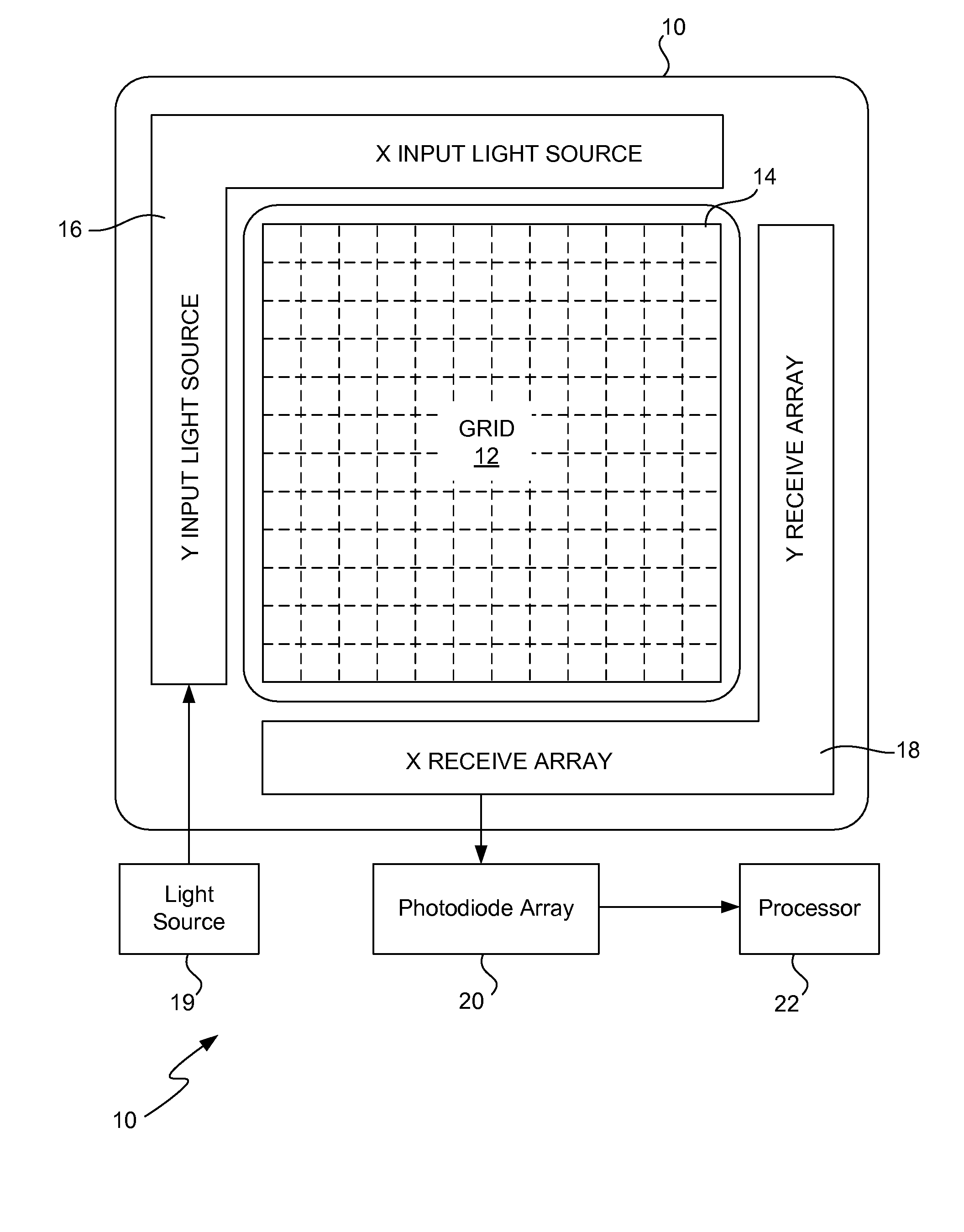
[0019]Referring to FIG. 1, a touch screen data input device is shown. The data input device 10 defines a “grid”12 of collimated light beams in the free space adjacent to a touch screen 14. The grid 12 (represented by the horizontal and vertical dashed lines) of light is created by a transmit polymer waveguide 16 provided on first X and Y sides of the screen 14. A receive polymer waveguide 18 is provided on the opposing X and Y sides of the screen 14 and is configured to receive the collimated beams of light. A light source 19, such as a laser diode, is optically coupled to the transmit waveguide 16. A photodiode array 20 is optically coupled to the individual waveguides of the receive polymer waveguide 18. A processor 22, which is coupled to the photodiode array 20, is provided to determine the X and Y coordinate of any interrupt in the grid 12 of collimated light caused during a data entry.

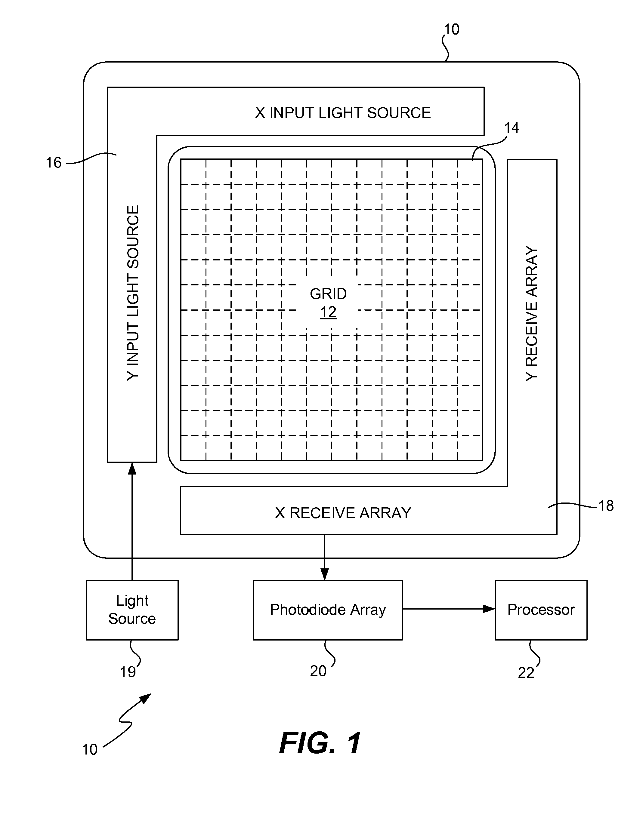
[0020]Referring to FIG. 2, a diagram illustrating the transmit waveguide 16 and the receive w...


PUM


Abstract

An optical based input touch display device with high resolution shadow detection using the linear splitting of waveguides among transmit and receive lenses and grey-scale calculations for shadow edge and center detection is disclosed. The apparatus includes a light source and a transmit waveguide optically coupled to the light source. The transmit waveguide includes a plurality of transmit waveguide grooves coupled to a plurality of groups of shared transmit lenses respectively. The plurality of groups of transit lenses, which are configured to generate a plurality of collimated light beams from the light source. A receive waveguide is also provided having a plurality of receive waveguide grooves coupled to a plurality of groups of shared receive lenses. The plurality of groups of receive lenses are configured to receive the plurality of collimated light beams. A photodiode array including a plurality of photodiodes are optically coupled to the plurality of receive waveguide grooves respectively. Each of the photodiodes is configured to receive light from the plurality of light beams received by the plurality of groups of receive lenses respectively. A processor is configured to detect shadow edge and / or shadow center of an interrupt in the plurality of collimated light beams.

Description

RELATED APPLICATIONS[0001]The present invention is related to U.S. application Ser. No. ______ (Attorney Docket No. NSC1P371 / P06764) entitled “Self-Timing Exposure Control for Optical Based Input Touch Display Devices” filed on the same day as the present application, and incorporated herein for all purposes.BACKGROUND[0002]1. Field of the Invention[0003]The present invention relates to optical based input touch display devices, and more particularly, to shadow detection for optical based input touch devices using linear splitting of optical beams and grey-scale calculations for detecting the shadow edge and center of an input device.[0004]2. Background of the Invention[0005]User input devices for data processing systems can take many forms. Two types of relevance are touch screens and pen-based screens. With either a touch screen or a pen-based screen, a user may input data by touching the display screen with an input device, such as a stylus, pen or finger.[0006]One conventional a...

Claims


Application Information

Patent Timeline
Patent Type & Authority Applications(United States)
IPC IPC(8): G06F3/042
CPCG06F3/0421Y10S385/901
Inventor DEANE, PETER
Owner POA SANA LIQUIDATING TRUST
Why Eureka
Try Eureka