Apparatus to enable an automobile driver to see above oversized vehicles and other obstacles

Inactive Publication Date: 2008-11-06
KAISER EVAN ROBERT
3 Cites 0 Cited by

AI-Extracted Technical Summary

Problems solved by technology

It is more difficult for drivers of these vehicles to see in and around their own vehicles—hence the need for rear-view cameras.
While prior technology increased a driver's visibility to the side, behind, and close by ...

Benefits of technology

[0013]In accordance with a preferred embodiment of the invention, there is disclosed an apparatus to enable an automobile driver to see above oversized vehicles and other obstacles comprising: a periscope that attaches to the roof and windshield or side window of a motor vehicle, a sleeve...

Abstract

An apparatus to enable an automobile driver to see above oversized vehicles and other obstacles with a periscope that attaches to the roof and windshield (or side window) of a motor vehicle, a sleeve mechanism that permits extension and rotation of the device, placement at the top of the windshield (or side window) that permits easy viewing, a powerful magnet and roof latch that secures the scope to the vehicle, and an optional zoom function that permits enlargement of a sighted object.: A preferred embodiment includes sturdy, weather-proof construction, availability in many colors, pre-assembly, and easy attachment.

Application Domain

Technology Topic

Image

  • Apparatus to enable an automobile driver to see above oversized vehicles and other obstacles
  • Apparatus to enable an automobile driver to see above oversized vehicles and other obstacles
  • Apparatus to enable an automobile driver to see above oversized vehicles and other obstacles

Examples

  • Experimental program(1)

Example

[0020]Detailed descriptions of the preferred embodiment are provided herein. It is to be understood, however, that the present invention may be embodied in various forms. Therefore, specific details disclosed herein are not to be interpreted as limiting, but rather as a basis for the claims and as a representative basis for teaching one skilled in the art to employ the present invention in virtually any appropriately detailed system, structure or manner.
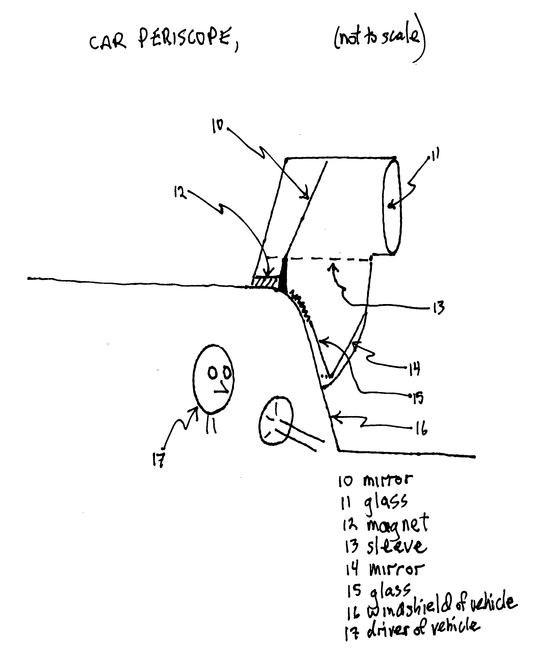
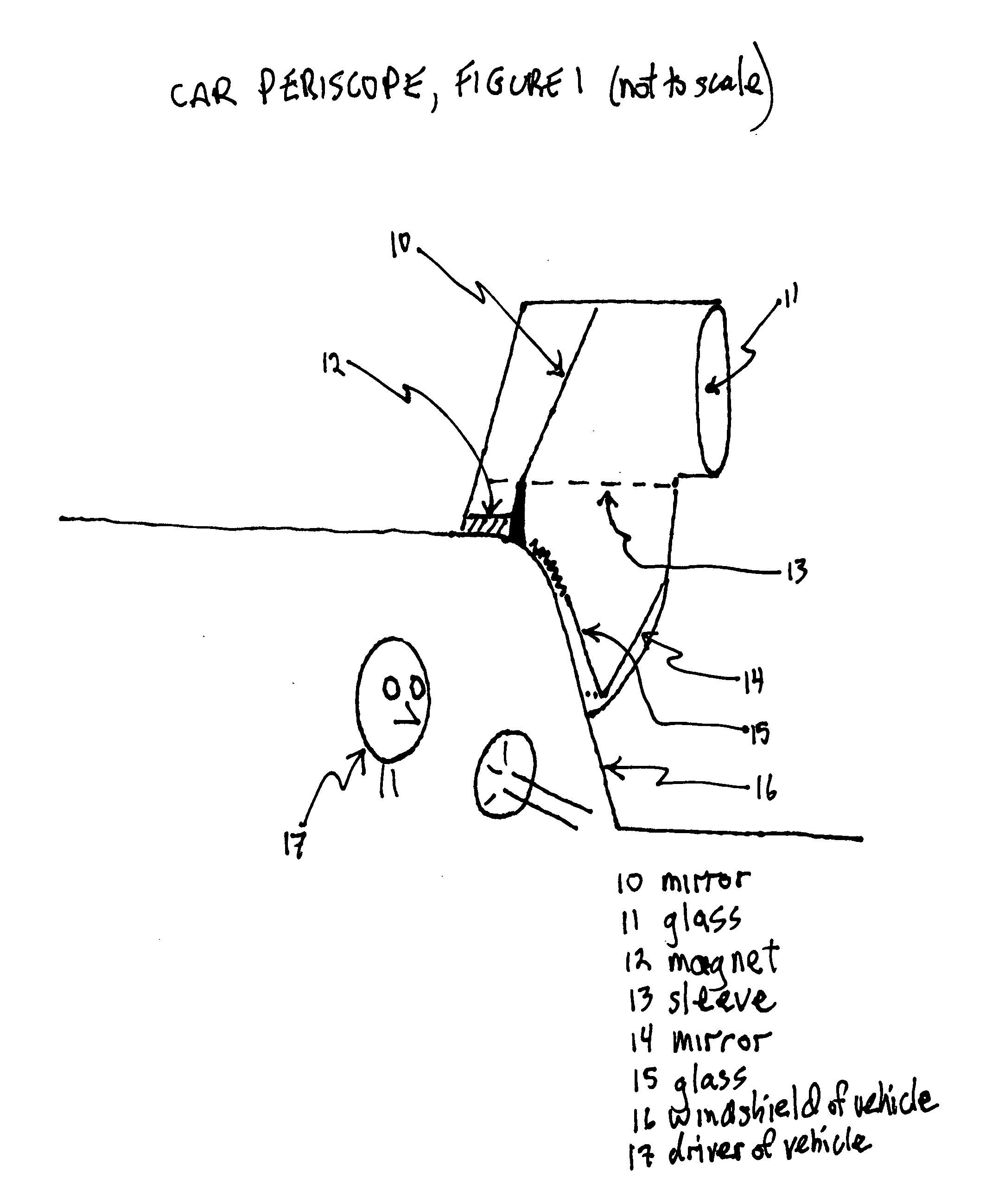
[0021]Turning to FIG. 1, one sees a cross section of a periscope that attaches to the roof and windshield of a motor vehicle. The device would be comprised of sturdy, all-weather materials and would be available in many colors in order to match commercially available automobiles. The mode of attachment in this embodiment is a powerful magnet (12) and roof latch that secures placement of the scope on the vehicle; alternatively, a kit to permit assembly and attachment of the device to the vehicle roof permanently with bolts could be included, or the periscope could be integrated in the vehicle's construction at the factory. The lens of the device sits high above the top of the vehicle, providing the driver with a high vantage point from which he can see past oversized vehicles and other obstacles. The mechanism permits light to enter the scope through the glass lens (11), reflect off of mirrors (10&14), penetrate the windshield or other window (15), and then be seen by the driver (17). The sleeve (13) permits rotation and extension of the telescope—full rotation could be permitted for rear viewing. A zoom apparatus might be optionally attached to the lens (11) to permit enlargement of sighted objects and therefore closer investigation of items of interest—this apparatus could be motorized, and permit shifting from normal view to wide-angle viewing.
[0022]Turning to FIG. 2, one sees a different perspective of the main embodiment of the invention.
[0023]Turning to FIG. 3, one sees a variation of the device comprising integration into the body of the vehicle.
[0024]Turning to FIG. 4, one sees a birds-eye perspective of an alternative embodiment of the invention, comprising a side mount, situated at the driver side window.
[0025]Turning now to FIG. 5, one sees the side mount variation of the device in a frontal view. The mechanism permits light to enter the scope through the glass lens (31), reflect off three mirrors (32, 34, &35), penetrate the side window, and then be seen by the driver (37).
[0026]Used as described above, the device will enable a driver to expand his range of vision and thereby surmount the challenge of oversized vehicles and other obstacles on today's roadways.
[0027]While the invention has been described in connection with a preferred embodiment, it is not intended to limit the scope of the invention to the particular form set forth, but on the contrary, it is intended to cover such alternatives, modifications, and equivalents as may be included within the spirit and scope of the invention as defined by the appended claims.

PUM

no PUM

Description & Claims & Application Information

We can also present the details of the Description, Claims and Application information to help users get a comprehensive understanding of the technical details of the patent, such as background art, summary of invention, brief description of drawings, description of embodiments, and other original content. On the other hand, users can also determine the specific scope of protection of the technology through the list of claims; as well as understand the changes in the life cycle of the technology with the presentation of the patent timeline. Login to view more.

Similar technology patents

Classification and recommendation of technical efficacy words

Why Eureka
Try Eureka