Electronic Watermark Embedding Method, Electronic Watermark Detecting Method, Electronic Watermark Detecting Apparatus and Program

a technology of electronic watermarks and embedding methods, applied in selective content distribution, television systems, instruments, etc., can solve problems such as unauthorized use of work, such as a recaptured image or video image, and the image quality of the target moving image degrades depending on the brightness of the frame image, so as to improve the reliability of detection results.

Active Publication Date: 2008-11-06
MITSUBISHI ELECTRIC CORP +1
View PDF17 Cites 30 Cited by
  • Summary
  • Abstract
  • Description
  • Claims
  • Application Information

AI Technical Summary

Benefits of technology

[0011]In accordance with an aspect of the present invention, there is provided an electronic watermark embedding method including: a dividing processing step of dividing an electronic image into which an electronic watermark is to be embedded into a plurality of image regions spatially; an adaptive extraction step of extracting, as adaptive pixels, pixels each having a property of being difficult to visually recognize a variation in a pixel value from each of the plurality of image regions; and an embedding step of producing a variation between the pixel values of the adaptive pixels in one of the plurality of image regions and those of the adaptive pixels in an adjacent one of the plurality of image regions, and varying the pixel values of the adaptive pixels of the plurality of image regions in a time direction, according to a value of an embedded bit set of an electronic watermark, and of generating an electronic-watermark-embedded image by making the variation in the pixel values of the adaptive pixels vary step by step at a boundary between the two of the plurality of image regions and / or in the time direction so that the variation makes a slow transition.
[0012]Therefore, the present invention offers an advantage of being able to maintain the resistance of the electronic watermark to recapturing of the target image to which the electronic watermark is embedded, and also to reduce the visual disturbance due to the embedding of the electronic watermark remarkably.
[0014]Therefore, the present invention offers an advantage of being able to improve the reliability of the detection result of the electronic watermark, and the accuracy of the detection of the electronic watermark.

Problems solved by technology

However, such technical improvements cause unauthorized use of work, such as a recaptured image or video image.
A problem with the prior art electronic watermark technology is, however, that depending on the target moving image into which the electronic watermark is embedded, a difference in the brightness between frame images, which is caused by the brightness variations with respect to the time direction which are provided for the target moving image, can be viewed as a light or dark portion while the moving image is played back.
A problem with the related art method is, however, that the image quality of the target moving image degrades depending upon the target moving image into which the electronic watermark is to be embedded.

Method used


Image

  • Electronic Watermark Embedding Method, Electronic Watermark Detecting Method, Electronic Watermark Detecting Apparatus and Program
  • Electronic Watermark Embedding Method, Electronic Watermark Detecting Method, Electronic Watermark Detecting Apparatus and Program
  • Electronic Watermark Embedding Method, Electronic Watermark Detecting Method, Electronic Watermark Detecting Apparatus and Program

Examples


embodiment 1

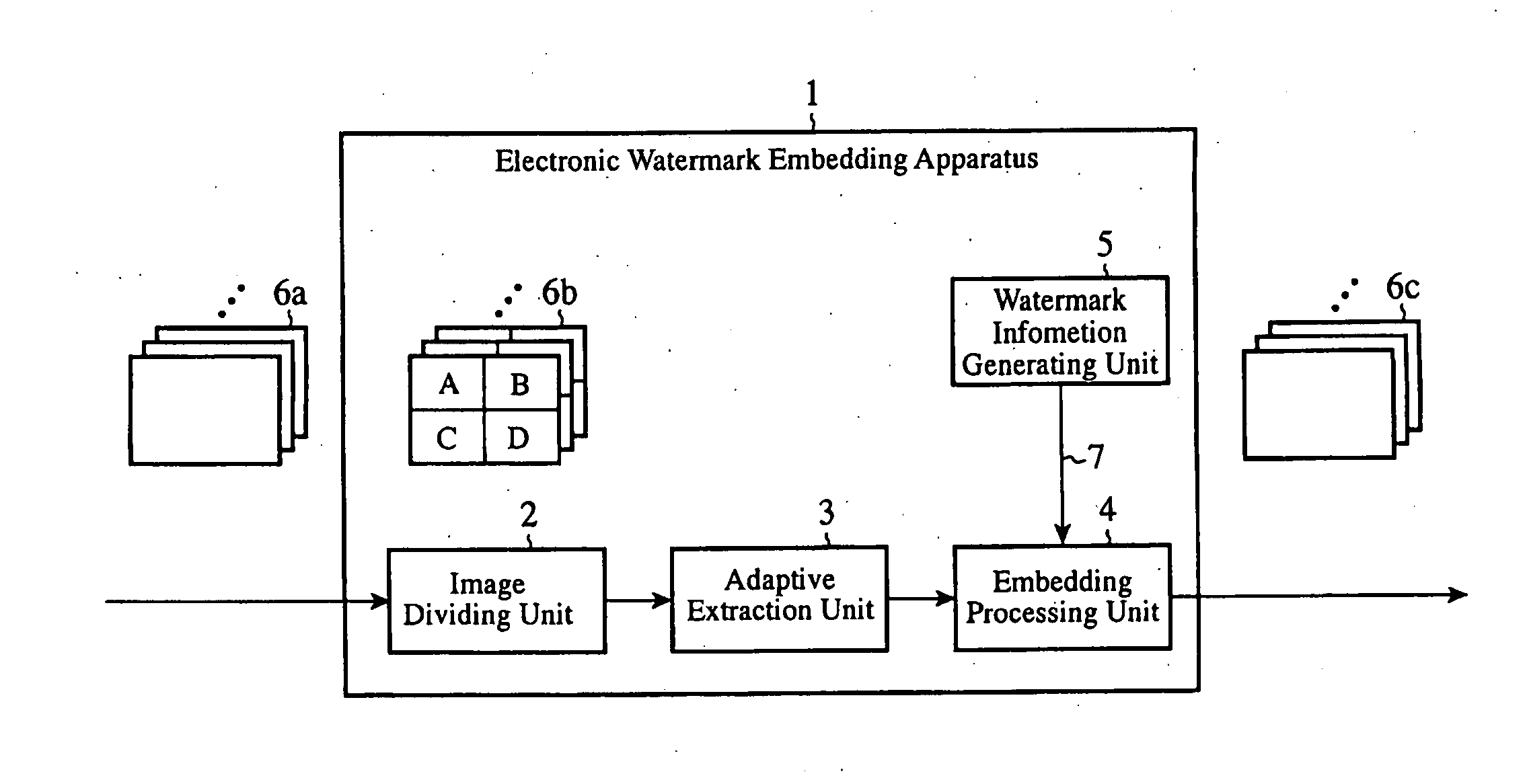
[0052]FIG. 1 is a block diagram showing the structure of an electronic watermark embedding apparatus in accordance with embodiment 1 of the present invention. The electronic watermark embedding apparatus 1 is provided with an image dividing unit 2, an adaptive extraction unit 3, an embedding processing unit 4, and a watermark information generating unit 5. The electronic watermark embedding apparatus 1 can be implemented via execution of an electronic watermark embedding program in accordance with the present invention by using, for example, a general-purpose computer.

[0053]In other words, the electronic watermark embedding apparatus 1 can carry out its characteristic data processing by making the computer execute the electronic watermark embedding program and function as the above-mentioned components 2 to 5. In the following explanation, since those skilled in the art can easily recognize the structure and fundamental functions of the computer which embodies the electronic waterma...

embodiment 2

[0099]In above-mentioned embodiment 1, there is provided an example of extracting adaptive pixels having a brightness value of 128 or more which corresponds to a brightness level at which the image quality of a target image does not degrade even if a process of producing brightness variations is performed on the adaptive pixels from the target image. However, there are cases where the extraction of only these adaptive-pixels does not provide an adequate amount of embedding and therefore no electronic watermark can be detected.

[0100]It is expected that there are many cases where in the target image into which the electronic watermark is to be embedded, pixels each having a large pixel value variation between frame images (or field images) form a frame image having abrupt movements of objects, and therefore pixel value variations have little visual influence upon such pixels.

[0101]An electronic watermark embedding apparatus in accordance with embodiment 2 detects pixels each having a ...

embodiment 3

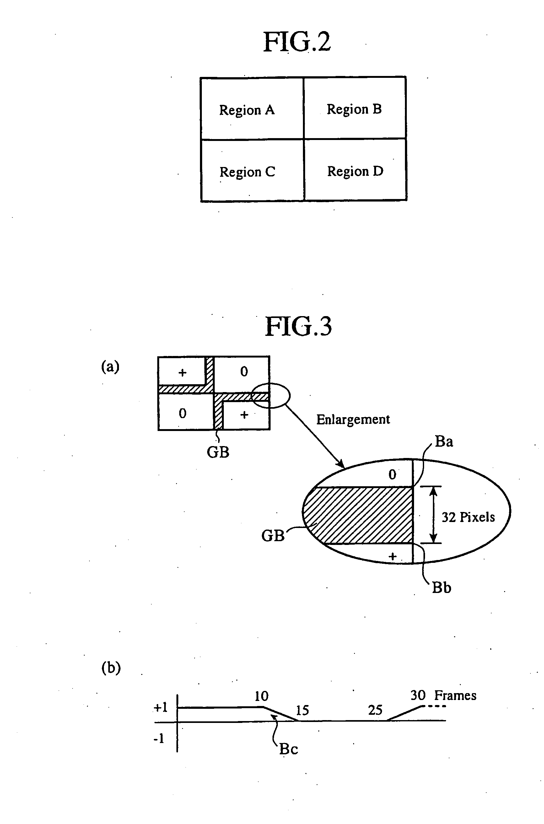
[0114]An electronic watermark embedding apparatus in accordance with this embodiment 3 selects, as adaptive pixels for embedding of an electronic watermark, pixels at an edge portion of a target image into which the electronic watermark is to be embedded in order to increase the amount of embedding of the electronic watermark.

[0115]The electronic watermark embedding device in accordance with embodiment 3 fundamentally has the same structure as that according to above-mentioned embodiment 1, but differs from that according to above-mentioned embodiment 1 in that an adaptive extraction unit 3 and an embedding processing unit 4 thereof perform edge adaptation processing on the target image.

[0116]Next, the selection of adaptive pixels in the edge adaptation processing will be explained.

[0117]First, the adaptive extraction unit 3 performs perpendicular edge filter processing, isolated-point removing processing, and three-point NAM processing on an electronic image 6b into which an electr...


PUM


Abstract

An electronic image into which an electronic watermark is to be embedded is divided into a plurality of image regions spatially, and pixels each having a property of being difficult to visually recognize a variation in a pixel value are extracted as adaptive pixels from each of the plurality of image regions. A variation between the pixel values of the adaptive pixels in one of the plurality of image regions and those of the adaptive pixels in an adjacent one of the plurality of image regions is produced, and the pixel values of the adaptive pixels of the plurality of image regions are varied in a time direction according to the value of an embedded bit set of the electronic watermark. An electronic-watermark-embedded image is then generated by making the variation in the pixel values of the adaptive pixels vary step by step at a boundary between the two of the plurality of image regions and / or in the time direction so that the variation makes a slow transition.

Description

FIELD OF THE INVENTION[0001]The present invention relates to an electronic watermark embedding method of and an electronic watermark detecting method of being able to detect an electronic watermark from a recaptured image acquired by recapturing an image displayed on a screen, such as a display's screen, and an apparatus and a program which use these methods.BACKGROUND OF THE INVENTION[0002]Improvements in the performance of television cameras in recent years and reduction in the costs of television cameras make it easy to recapture an image or video image displayed on a screen, such as a display's screen, with a sufficient image quality. However, such technical improvements cause unauthorized use of work, such as a recaptured image or video image. For example, there have been reported cases where a video image screened in a movie theater was recaptured directly with a digital camera, and was copied to a medium, such as a DVD (Digital Versatile Disk), and the medium was on sale ille...

Claims


Application Information

Patent Timeline
Patent Type & Authority Applications(United States)
IPC IPC(8): G06K9/00H04N7/08G06T1/00H04N1/387H04N19/00H04N19/467H04N19/70H04N19/85
CPCG06T1/0028G06T2201/0051G06T2201/0061H04N19/467H04N1/32229H04N2201/3233H04N2201/327H04N1/32208H04N1/387H04N5/913H04N21/8358
Inventor FUJII, RYOUSUKEITO, HIROSHIMAGAI, KOUICHISUZUKI, MITSUYOSHIWADA, MINORUOHTAKE, GOGOSHI, SEIICHI
Owner MITSUBISHI ELECTRIC CORP
Why Eureka
Try Eureka