Dielectric ceramic composition and electronic device

a technology of dielectric ceramics and electronic devices, applied in the direction of fixed capacitors, basic electric elements, electrical appliances, etc., can solve the problems of increasing environmental conditions of electronic devices, reducing the specific permittivity of electronic devices, and reducing the use of precious metals. , to achieve the effect of reducing the atmosphere, reducing the cost of materials, and maintaining a lifetime of insulation resistan

Active Publication Date: 2007-08-28
TDK CORPARATION
View PDF20 Cites 23 Cited by
  • Summary
  • Abstract
  • Description
  • Claims
  • Application Information

AI Technical Summary

Benefits of technology

[0015]An object of the present invention is to provide a dielectric ceramic composition having a high specific permittivity, capable of maintaining a lifetime of insulation resistance and satisfying the X8R characteristics (−55 to 150° C. and ΔC / C=within ±15%) of EIA standard, able to be fired in a reducing atmosphere and having improved IR temperature dependency. Another object of the present invention is to provide an electronic device, such as a multilayer ceramic capacitor, using the dielectric ceramic composition and capable of realizing a compact body with a large capacity, particularly, being ready for attaining a thin layer compact body.

Problems solved by technology

Recently, there is a tendency of reducing a wire harness for connecting the electronic apparatus and an apparatus to be controlled thereby and the electronic apparatus may be provided outside of a vehicle, therefore, environments for the electronic apparatuses have been getting more severe.
Therefore, there is a disadvantage that inexpensive base metals, such as Ni, cannot be used for internal electrodes of the capacitor and expensive precious metals, such as Pd, Au and Ag, have to be used.
However, although the X8R characteristics are satisfied, the IR temperature dependency from the room temperature to a high temperature range was poor and the practical use as a product has sometimes become difficult.

Method used


Image

  • Dielectric ceramic composition and electronic device
  • Dielectric ceramic composition and electronic device
  • Dielectric ceramic composition and electronic device

Examples


first embodiment

[0084]Below, a first embodiment of the present invention will be explained.

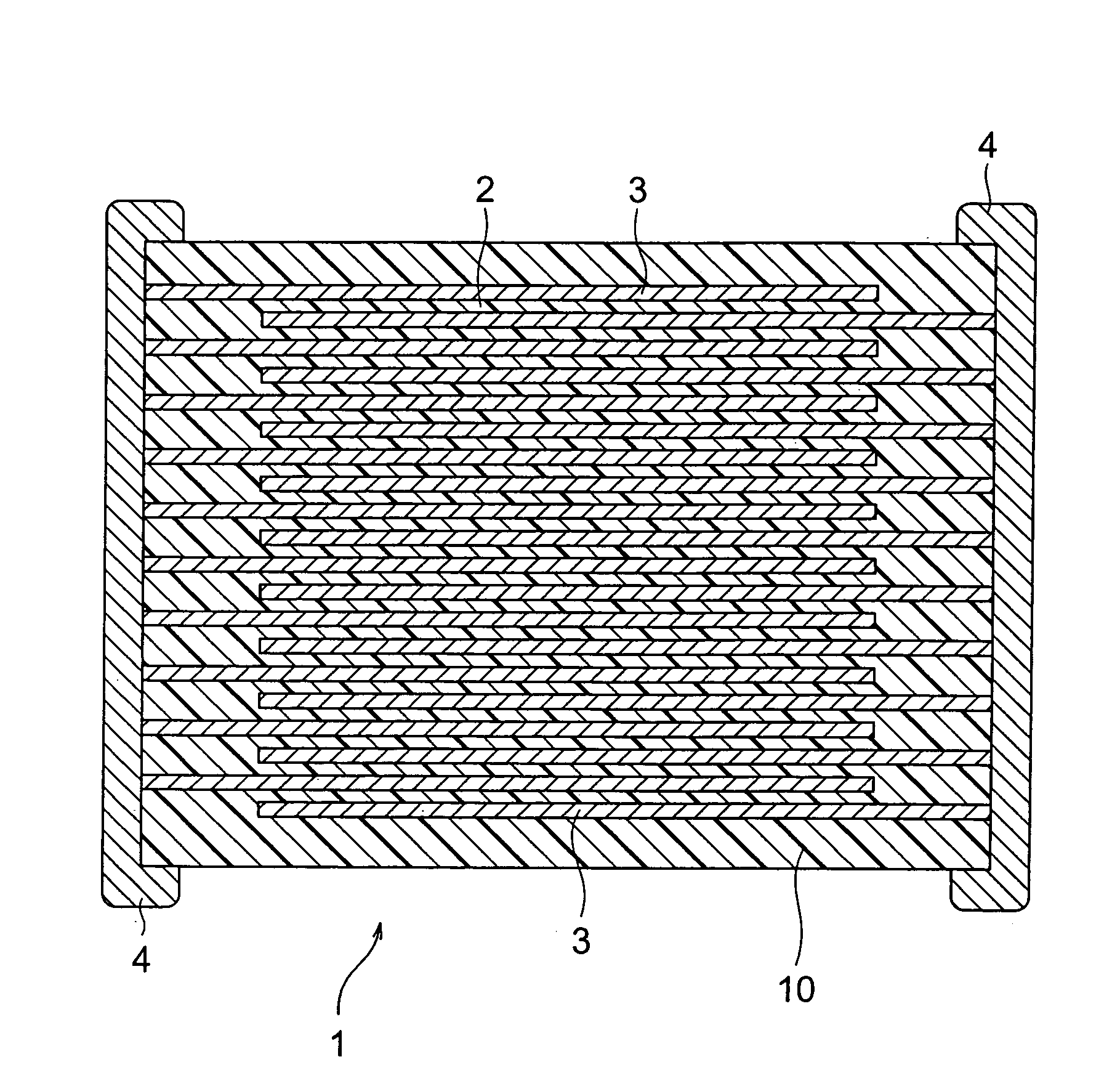
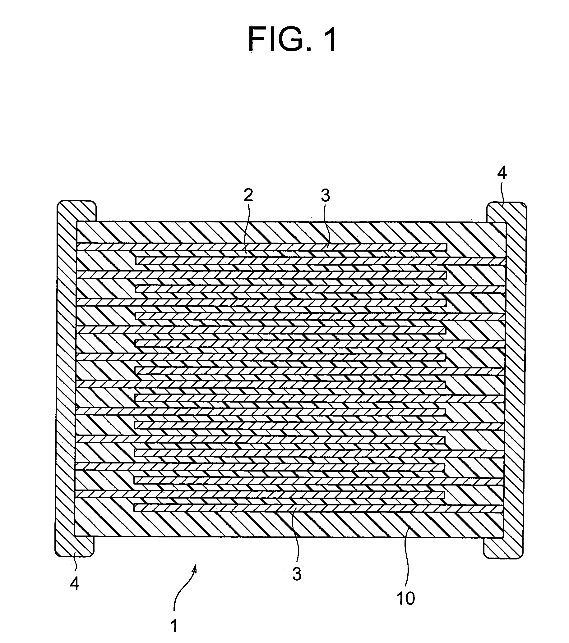
[0085]In the first embodiment, a multilayer ceramic capacitor 1 shown in FIG. 1 as an electronic device will be taken as an example and the configuration and production method will be explained.

[0086]Multilayer Ceramic Capacitor

[0087]As shown in FIG. 1, a multilayer ceramic capacitor 1 as an electronic device according to the first embodiment of the present invention comprises a capacitor element body 10, wherein dielectric layers 2 and internal electrode layers 3 are alternately stacked. Both end portions of the capacitor element body 10 are formed with a pair of external electrodes 4 respectively conducting to the internal electrode layers 3 arranged alternately in the element body 10. The internal electrode layers 3 are stacked, so that the respective end surfaces are exposed alternately to surfaces of two facing end portions of the capacitor element body 10. The pair of external electrodes 4 are formed on...

second embodiment

[0169]Below, a second embodiment of the present invention will be explained.

[0170]In the same way as in the first embodiment, a multilayer ceramic capacitor 1 shown in FIG. 1 will be taken as an example of an electronic device and the configuration and production method will be explained in the second embodiment, as well.

[0171]In the second embodiment, the point that the dielectric layer 2 includes a dielectric ceramic composition according to the second embodiment is different from the first embodiment.

[0172]The most significant feature of the dielectric ceramic composition according to the second aspect is that it is essential to include MgO as the first subcomponent and Al2O3 as the eighth subcomponent, and a content of MgO as the first subcomponent and a content of MnO or Cr2O3 are in the above relationship explained above.

[0173]Note that an explanation will be omitted on overlapping parts with the first embodiment and only different parts will be explained.

[0174]Dielectric Laye...

example 1

[0201]Below, examples 1 and 2 and a comparative example 1 are examples according to the first aspect of the present invention.

[0202]First, as starting materials to produce a dielectric material, a main component material (BaTiO3) having an average particle diameter of 0.1 to 1 μm and the first to eighth subcomponent materials were prepared.

[0203]Carbonates were used as a material of MgO and MnO (the first subcomponent: MgCO3 and the seventh subcomponent: MnCO3) and oxides were used for other materials (the second subcomponent: (Ba0.6 Ca0.4)SiO3, the third subcomponent: V2O5, the fourth subcomponent: Yb2O3, the fifth subcomponent: CaZrO3, the sixth subcomponent: Y2O3 and the eighth subcomponent: Al2O3). Note that (Ba0.6 Ca0.4)SiO3, as the second subcomponent was produced by wet mixing BaCO3, CaCO3 and SiO2 by a ball mill for 16 hours, drying, firing at 1150° C. in the air and furthermore wet mixing by a ball mill for 100 hours. Also, CaZrO3 as the fifth subcomponent was produced by w...


PUM

PropertyMeasurementUnit
ionic radiusaaaaaaaaaa
temperatureaaaaaaaaaa

Abstract

A dielectric ceramic composition, comprising a main component including barium titanate; a first subcomponent including at least one kind selected from MgO, CaO, BaO and SrO; a second subcomponent functioning as a sintering auxiliary agent; a third subcomponent including at least one kind selected from V2O5, MoO3 and WO3; a fourth subcomponent including an oxide of R1 (note that R1 is at least one kind selected from Sc, Er, Tm Yb and Lu); a fifth subcomponent including CaZrO3 or CaO+ZrO2; and an eighth subcomponent including an oxide of A (note that A is at least one kind selected from a cation element group having an effective ionic radius at the time of 6 coordination of 0.065 nm to 0.085 nm); wherein a ratio of the eighth subcomponent with respect to 100 moles of the main component is 0 to 4 moles (note that 0 mole and 4 moles are excluded, and the value is in terms of an A oxide).

Description

BACKGROUND OF THE INVENTION[0001]1. Field of the Invention[0002]The present invention relates to a dielectric ceramic composition having reduction resistance and an electronic device, such as a multilayer ceramic capacitor, using the dielectric ceramic composition.[0003]2. Description of the Related Art[0004]A multilayer ceramic capacitor as an electronic device is required to have a high specific permittivity, long lifetime of insulation resistance IR and preferable DC bias characteristics (change of specific permittivity over time is a little) and, moreover, required to have preferable temperature characteristics. Particularly, depending on the use object, the temperature characteristics are required to be flat under severe conditions. In recent years, multilayer ceramic capacitors have come to be used in a variety of electronic apparatuses mounted in engine compartments of automobiles, such as an electronic control unit (ECU), a crank angle sensor and an Anti Lock Brake System (A...

Claims


Application Information

Patent Timeline
Patent Type & Authority Patents(United States)
IPC IPC(8): C04B35/468H01G4/12
CPCC04B35/4682C04B35/62665C04B35/6303C04B35/64H01G4/1227B32B2311/22C04B2235/3201C04B2235/3203C04B2235/3206C04B2235/3208C04B2235/3213C04B2235/3215C04B2235/3217C04B2235/3224C04B2235/3225C04B2235/3239C04B2235/3241C04B2235/3256C04B2235/3258C04B2235/3262C04B2235/3286C04B2235/3287C04B2235/3409C04B2235/3418C04B2235/3436C04B2235/3454C04B2235/447C04B2235/5445C04B2235/6582C04B2235/6584C04B2235/6588C04B2235/662C04B2235/79C04B2237/346C04B2237/405C04B35/468
Inventor ITO, KAZUSHIGESATO, AKIRA
Owner TDK CORPARATION
Why Eureka
Try Eureka