Dielectric composition and electronic component

a technology of dielectric composition and electronic components, applied in the direction of fixed capacitors, thin/thick film capacitors, electrical equipment, etc., can solve the problems of difficult to achieve high dc breakdown voltage and ac breakdown voltage, and the circuit has rapidly become more compact and complicated, and achieves low dielectric loss, small heat generating property, and high specific permittivity

Active Publication Date: 2020-07-14
TDK CORPARATION
View PDF9 Cites 0 Cited by
  • Summary
  • Abstract
  • Description
  • Claims
  • Application Information

AI Technical Summary

Benefits of technology

[0007]The object of the present invention is to provide a dielectric composition having high specific permittivity, and DC breakdown voltage and AC breakdown voltage, a low dielectric loss, and a good temperature property even though lead is substantially not used, and also to provide an electronic component including the dielectric composition.
[0037]The dielectric composition of the present invention can attain high specific permittivity, DC breakdown voltage, and AC breakdown voltage, a low dielectric loss, a small heat generating property, and good temperature property and heat generating property, even though lead is not substantially used.

Problems solved by technology

In recent years, electronic devices have rapidly attained higher-performances, and along with that electronic circuits have rapidly become more compact and more complicated.
However, the dielectric composition includes lead hence it was a problem from environmental point of view.
A conventional BaTiO3—BaZrO3—CaTiO3—SrTiO3 based dielectric ceramic composition has strong permittivity, thus it was difficult to attain high DC breakdown voltage and AC breakdown voltage while maintaining high capacitance and low dielectric loss.

Method used


Image

  • Dielectric composition and electronic component
  • Dielectric composition and electronic component
  • Dielectric composition and electronic component

Examples


first embodiment

[0047]The dielectric composition according to the first embodiment of the present invention includes Ba, Ca, Bi, Ti, and Sr. When characteristic X ray intensity derived from Sr is measured by EPMA, the dielectric composition includes two phases having different Sr characteristic X ray intensities. This indicates that two phases having different Sr concentrations are included in the dielectric composition.

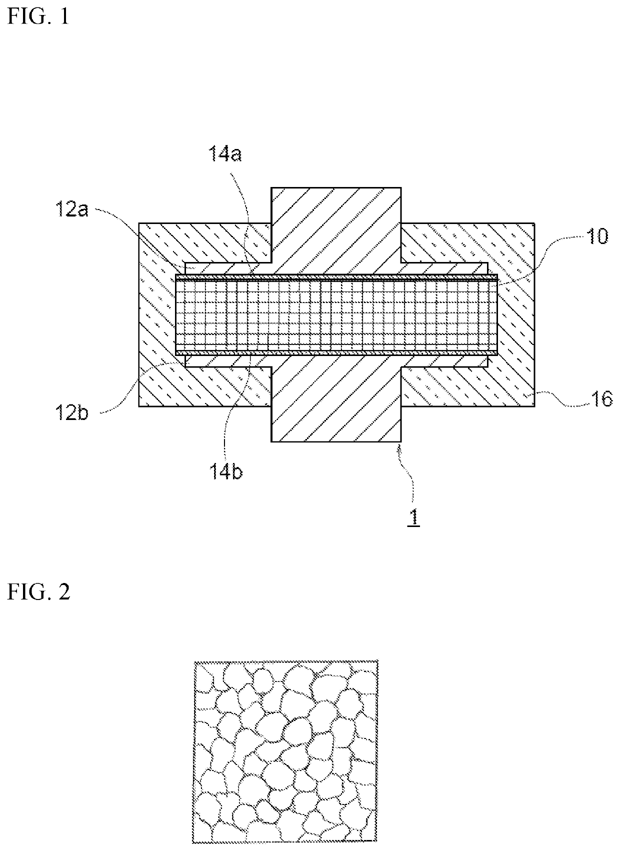
[0048]EPMA observation is done by mirror polishing a cross section of the dielectric composition after sintering (sintered body) which has been cut, then an image of the mirror polished face is taken by Scanning Electron Microscope (SEM). Further, EPMA (Electron Probe Micro Analyzer) is used to observe the same observation field as the SEM image, then mapping analysis of Sr (strontium) is carried out. Mapping by EPMA is carried out by measuring the intensity of the characteristic X ray derived from Sr.

[0049]SEM image is taken and also EPMA mapping analysis is carried out to the obse...

second embodiment

[0075]The dielectric composition according to the second embodiment of the present invention includes Ba, Ca, Bi, Ti, and Sr. The dielectric composition includes three phases having different Sr characteristic X ray intensities when the characteristic X ray intensity derived from Sr is measured by EPMA.

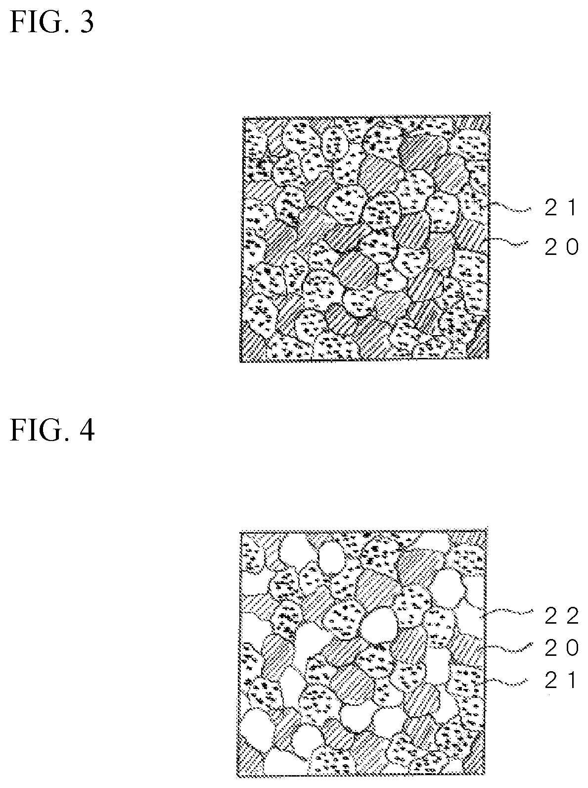
[0076]EPMA observation, SEM observation, element mapping, and the like are done as similar to the above. FIG. 4 shows a schematic diagram of Sr mapping of the dielectric composition according to the second embodiment. In FIG. 4, a particle 20 indicated by oblique lines is a phase having relatively low Sr characteristic X ray intensity (low Sr phase), and a particle 21 indicated by dots is a phase having relatively high Sr characteristic X ray intensity (high Sr phase). Also, the particle with no special marks has Sr characteristic X ray intensity which is between the low Sr phase and the high Sr phase, and hereinafter it may be referred as “intermediate Sr phase”.

[0077]The three phase...

examples

[0139]Hereinafter, the present invention will be described in further detail based on examples, but the present invention is not to be limited thereto.


PUM

PropertyMeasurementUnit
crystal particle sizeaaaaaaaaaa
X ray intensityaaaaaaaaaa

Abstract

The object of the present invention is to provide the dielectric composition having good specific permittivity, high DC breakdown voltage and AC breakdown voltage, small dielectric loss and heat generating property, and good temperature property even though lead is not substantially used. A dielectric composition of the first aspect includes a, Ca, Bi, Ti, and Sr, wherein the dielectric composition includes two phases having different Sr characteristic X ray intensities when a characteristic X ray intensity derived from Sr is measured by EPMA, and when Sr1 represents the characteristic X ray intensity derived from Sr of a first phase measured by EPMA and Sr2 represents the characteristic X ray intensity derived from Sr of a second phase measured by EPMA, a ratio (Sr2 / Sr1) of Sr2 with respect to Sr1 satisfies 2 or larger. A dielectric composition of the second aspect includes Ba, Ca, Bi, Ti, and Sr, wherein the dielectric composition includes three phases having different Sr characteristic X ray intensities when a characteristic X ray intensity derived from Sr is measured by EPMA, and when Sr1 represents the characteristic X ray intensity derived from Sr of a first phase measured by EPMA, Sr2 represents the characteristic X ray intensity derived from Sr of a second phase measured by EPMA, and Sr3 represents the characteristic X ray intensity derived from Sr of a third phase measured by EPMA, an intensity ratio (Sr1 / Sr3) of Sr1 with respect to Sr3 is 0.6 or less and an intensity ratio (Sr2 / Sr3) of Sr2 with respect to Sr3 is 1.4 or more.

Description

BACKGROUND OF THE INVENTION[0001]The present invention relates to a dielectric composition and an electronic component.[0002]In recent years, electronic devices have rapidly attained higher-performances, and along with that electronic circuits have rapidly become more compact and more complicated. Thus, electronic components are also demanded to become even more compact and to attain even higher performance. That is, the dielectric composition and the electronic component having high specific permittivity with low loss, and generating only small amount of heat, attaining high AC breakdown voltage and DC break down voltage in order to be used under high voltage, and also attaining a good temperature property are demanded.[0003]In order to correspond to the above demands, Patent Document 1 discloses PbTiO3—SrTiO3—Bi2Ti3O9 based dielectric composition. However, the dielectric composition includes lead hence it was a problem from environmental point of view.[0004]Also, as the dielectric...

Claims


Application Information

Patent Timeline
Patent Type & Authority Patents(United States)
IPC IPC(8): C04B35/468C04B35/475H01G4/12C04B35/47C04B35/453
CPCC04B35/47C04B35/4682C04B35/475H01G4/1227C04B2235/3236C04B2235/5445C04B2235/5436C04B35/468C04B2235/442C04B2235/3241C04B2235/3272C04B2235/3293C04B2235/3251C04B2235/3224C04B2235/96C04B2235/80C04B2235/785C04B2235/786C04B2235/768C04B35/62685C04B2235/3215C04B2235/3213C04B2235/3234C04B2235/3298C04B2235/3208C04B2235/3262C04B2235/656H01G4/33H01L28/55H01G4/30
Inventor OHTSU, DAISUKEMASAI, TAKUHAILONG, LIULIPING, LIANG
Owner TDK CORPARATION
Why Eureka
Try Eureka