Clamp Assembly for Sliding Clamp

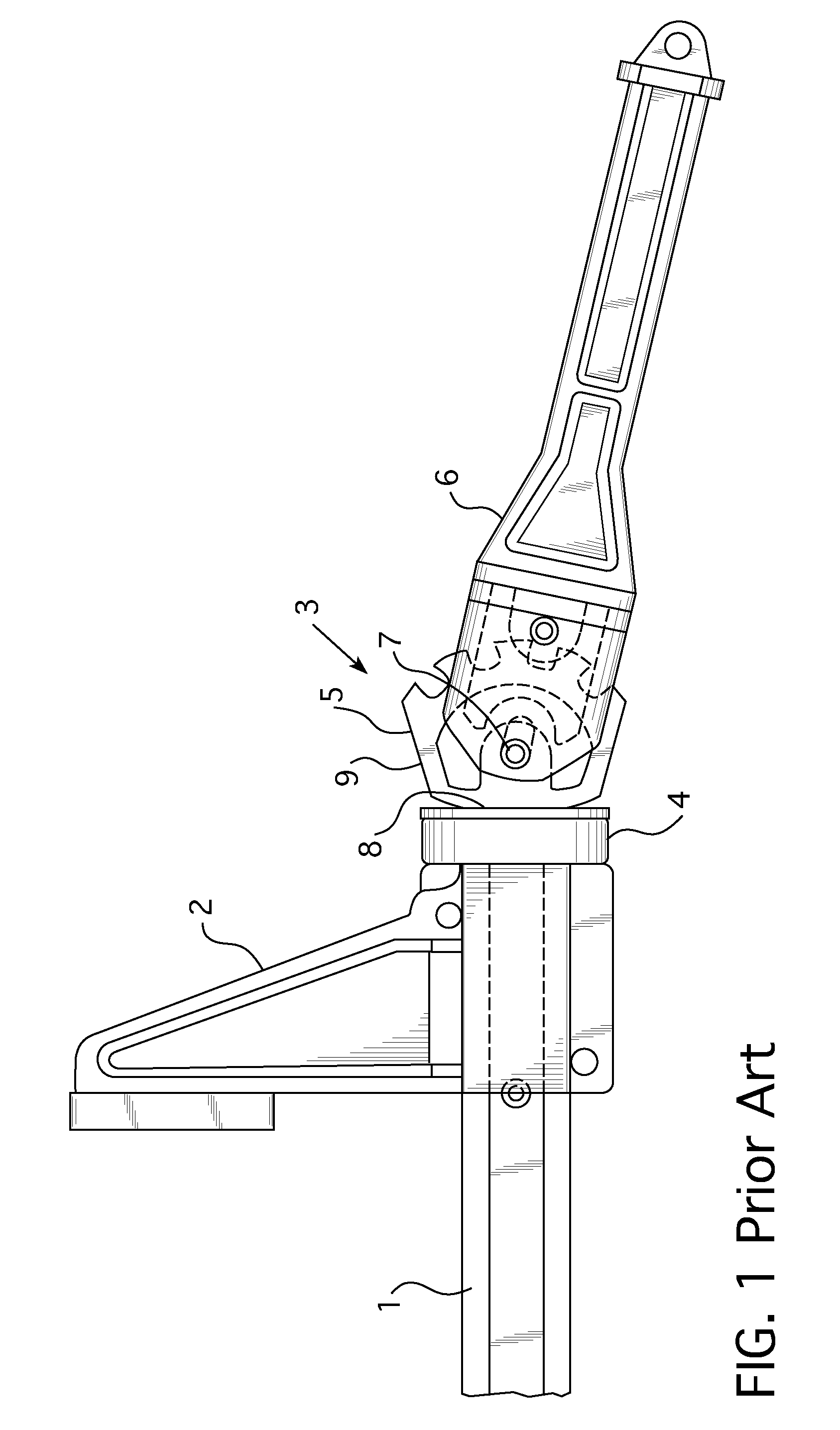
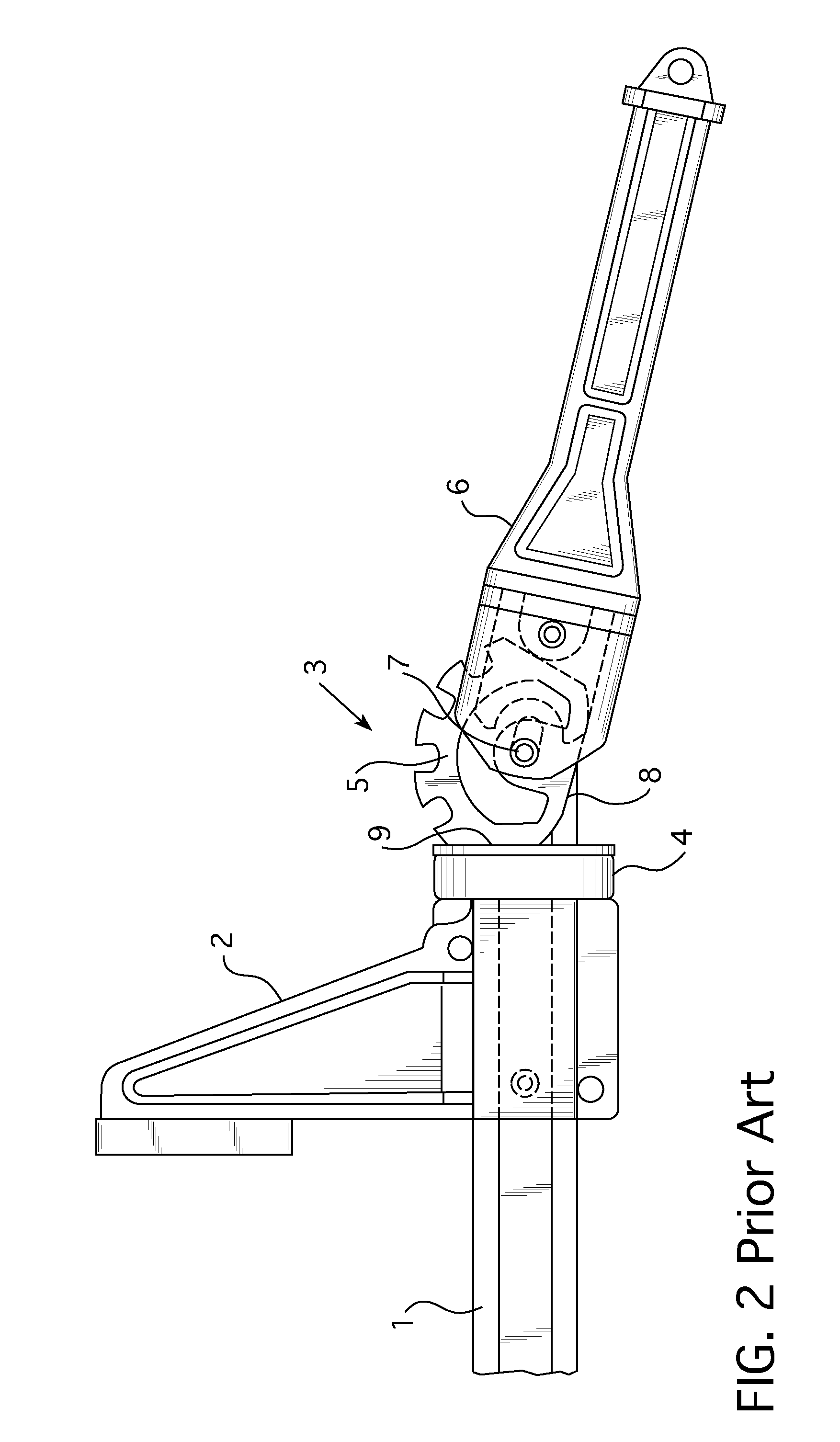
a technology of sliding clamps and clamping parts, which is applied in the field of sliding clamps, can solve the problems of the cam actuator b>6/b>, the cam member b>5/b> and the cam actuator b>5/b> pivoting about a stationary axis, and the object is not securely clamped between the jaws

Inactive Publication Date: 2008-11-13
PENN UNITED TECH
View PDF4 Cites 4 Cited by
  • Summary
  • Abstract
  • Description
  • Claims
  • Application Information

AI Technical Summary

Benefits of technology

[0011]Unlike the prior art, the cam member is coupled to the bar via a ball-and-socket coupling; therefore, the cam member and the cam actuator are fr...

Problems solved by technology

That is, while the jaws, which have been biased against the object with manual force, may hold the object, the object is not securely clamped between the jaws.
The disadvantage to this configuration is that the cam ...

Method used


Image

  • Clamp Assembly for Sliding Clamp
  • Clamp Assembly for Sliding Clamp
  • Clamp Assembly for Sliding Clamp

Examples


Embodiment Construction

[0019]As used herein, “coupled” means a link between two or more elements, whether direct or indirect, so long as a link occurs.

[0020]As used herein, “directly coupled” means that two elements are directly in contact with each other.

[0021]As used herein, “fixedly coupled” or “fixed” means that two components are coupled so as to move as one while maintaining a constant orientation relative to each other.

[0022]As used herein, “rotatably fixed” means that two components are coupled so as to move as one and maintain a generally constant position relative to each other, however the components may rotate relative to each other. For example, a bicycle tire is “rotatably fixed” to the bicycle frame; while the tire may rotate, the tire still moves with, and maintains a generally constant position relative to, the frame.

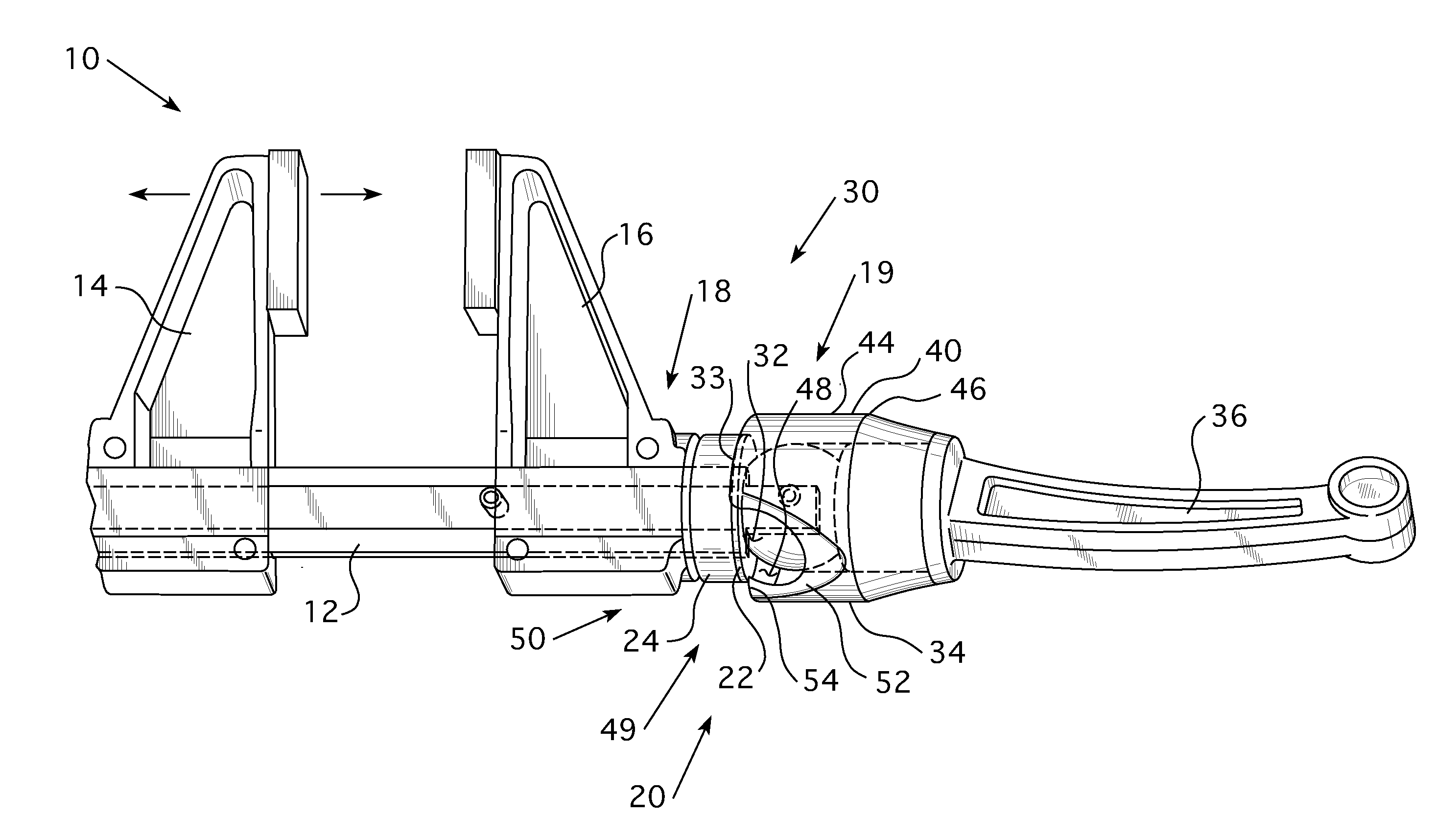
[0023]As shown in FIG. 3-6, a sliding clamp 10 includes an elongated bar 12, a sliding jaw assembly 14 (FIG. 3), a stationary jaw assembly 16, and a clamp assembly 30. The sl...


PUM


Abstract

A sliding clamp and clamp assembly are provided. The clamp assembly includes a cam member that, when actuated, biases a stationary clamp jaw assembly toward another jaw assembly. The cam member utilizes a ball-and-socket coupling to couple the cam member to the sliding clamp bar. The ball-and-socket coupling allows the cam member, and an extended actuator, to be pivoted and rotated into an infinite number of positions.

Description

CROSS REFERENCE TO RELATED APPLICATION [0001]This application claims priority under 35 U.S.C. §119(e) to U.S. Provisional Patent Application Ser. No. 60 / 916,409, filed May 7, 2007 entitled, CLAMP ASSEMBLY FOR SLIDING CLAMP.BACKGROUND OF THE INVENTION[0002]1. Field of the Invention[0003]This invention relates to a sliding clamp and, more specifically, to an improved clamping assembly for a sliding clamp.[0004]2. Background Information[0005]As shown in FIGS. 1 and 2, a sliding clamp typically includes an elongated bar 1, a stationary jaw assembly 2, and a clamp assembly 3. The sliding clamp further includes a sliding jaw (not shown). The two jaw assemblies are coupled to the bar 1. The sliding jaw assembly is structured to slide over, essentially, the length of the bar. The sliding jaw assembly includes a locking assembly structured to limit the direction of travel of the sliding jaw assembly. That is, when the locking assembly is engaged, the sliding jaw assembly may not be moved awa...

Claims


Application Information

Patent Timeline
IPC IPC(8): B25B5/08
CPCB25B1/08B25B5/085
Inventor PHILLIPS, SR., CHARLES M.NOAH, MARK P.
Owner PENN UNITED TECH
Why Eureka
Try Eureka