Method of Verifiably Detecting the Speed of a Vehicle

a vehicle speed and verification technology, applied in the direction of measuring devices, using reradiation, instruments, etc., can solve the problems of high degree of technical complexity, inability to identify a vehicle in a group of vehicles solely on the basis of individual distances measured, and high degree of sequence control of the measuring process

Active Publication Date: 2008-11-13
JENOPTIK ROBOT GMBH
View PDF25 Cites 41 Cited by
  • Summary
  • Abstract
  • Description
  • Claims
  • Application Information

AI Technical Summary

Benefits of technology

[0018]Thus, the problem to be solved by the present invention is to make available a method by means of which a detected vehicle in a group of vehicles can be identified regardless of features of the road or other environmental features.
[0019]This problem is solved by a method with the features of claim 1. Useful embodiments are described in the dependent claims.

Problems solved by technology

For high resolutions, a sequence control of the measuring process therefore entails a high degree of technical complexity.
An unequivocal identification of a vehicle in a group of vehicles solely on the basis of individual distances measured which are linked to a lane is not possible because of the potential ambiguities due to different reflection properties of the vehicles and potential multiple reflections.
Even if at each measuring moment a mean value is generated from the sum of the measured values, this mean value cannot always be unequivocally linked to a lane.
Although this measure excludes a the risk of falsifying the average distance measured due to partial reflections from parasitic reflectors, an identification based on the mean distance measured and its link to a road is not possible for each measuring situation.
However, the distance ranges shift if the vehicles do no drive exactly in the center of the lane and will overlap every time a vehicle within the measuring range changes lanes.
This leads to measuring situations in which a vehicle cannot be unequivocally linked to a lane, which means that the lane is not a reliable characteristic for identifying a vehicle in a group of vehicles.

Method used


Image

  • Method of Verifiably Detecting the Speed of a Vehicle
  • Method of Verifiably Detecting the Speed of a Vehicle
  • Method of Verifiably Detecting the Speed of a Vehicle

Examples


Embodiment Construction

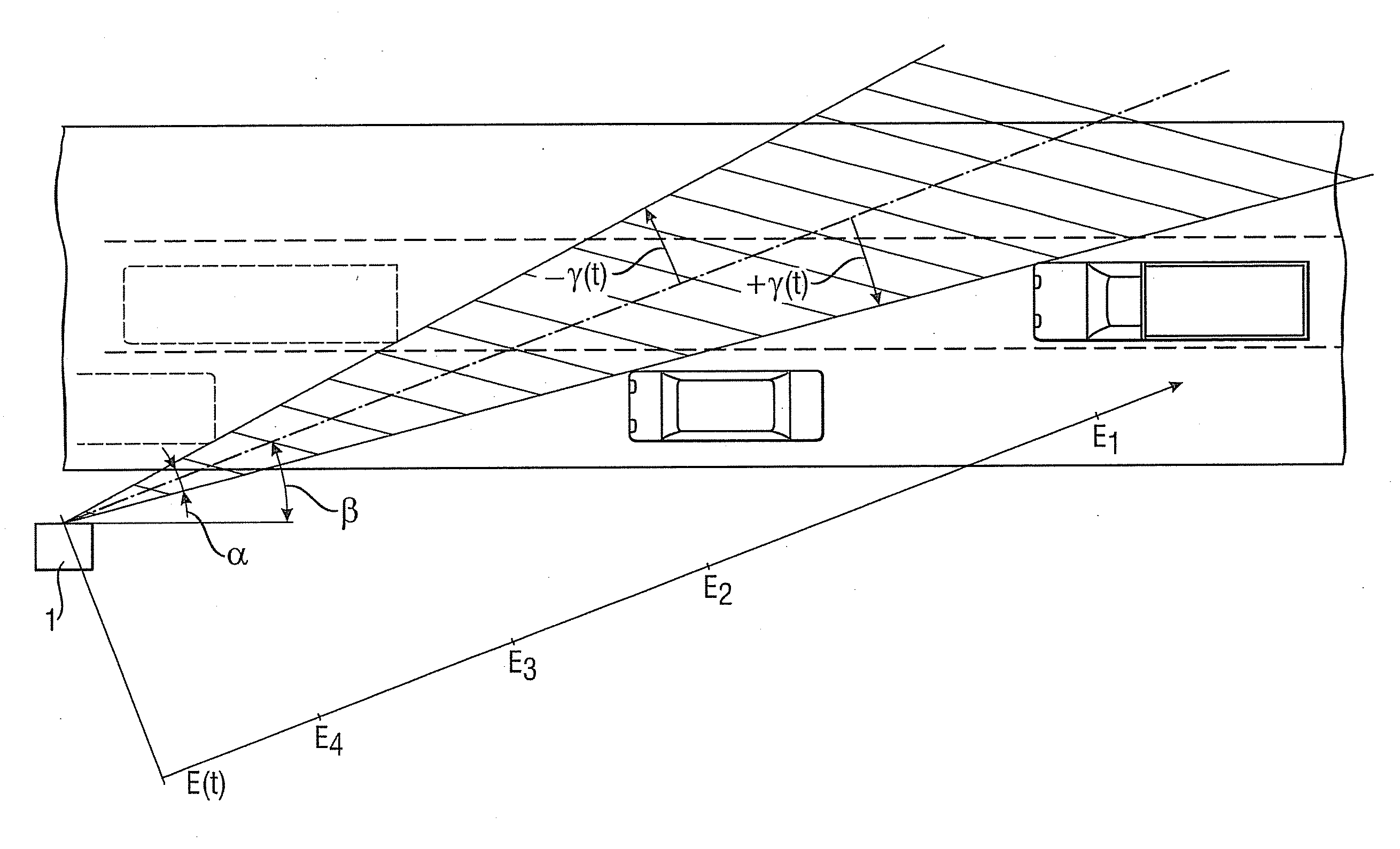
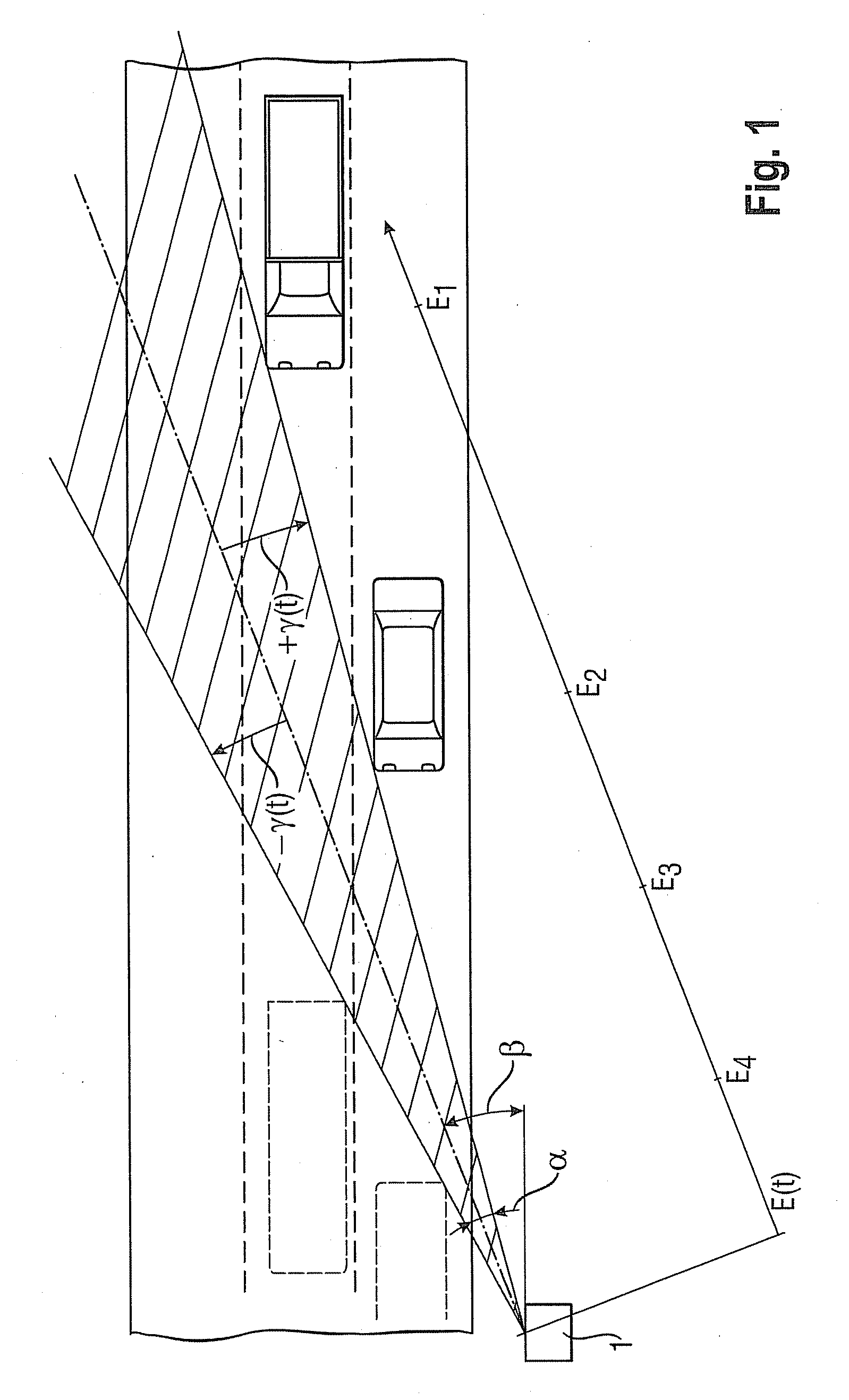
[0023]To describe a first practical example based on FIG. 1, it will be assumed that a radar system 1 which emits a radar beam with an aperture angle a is positioned on the side of the road at an acute horizontal positioning angle B of the radar axis relative to the direction of the road on the side of a road [sic with multiple lanes. The positioning angle B can also be formed by an angle of squint of the radar antenna.

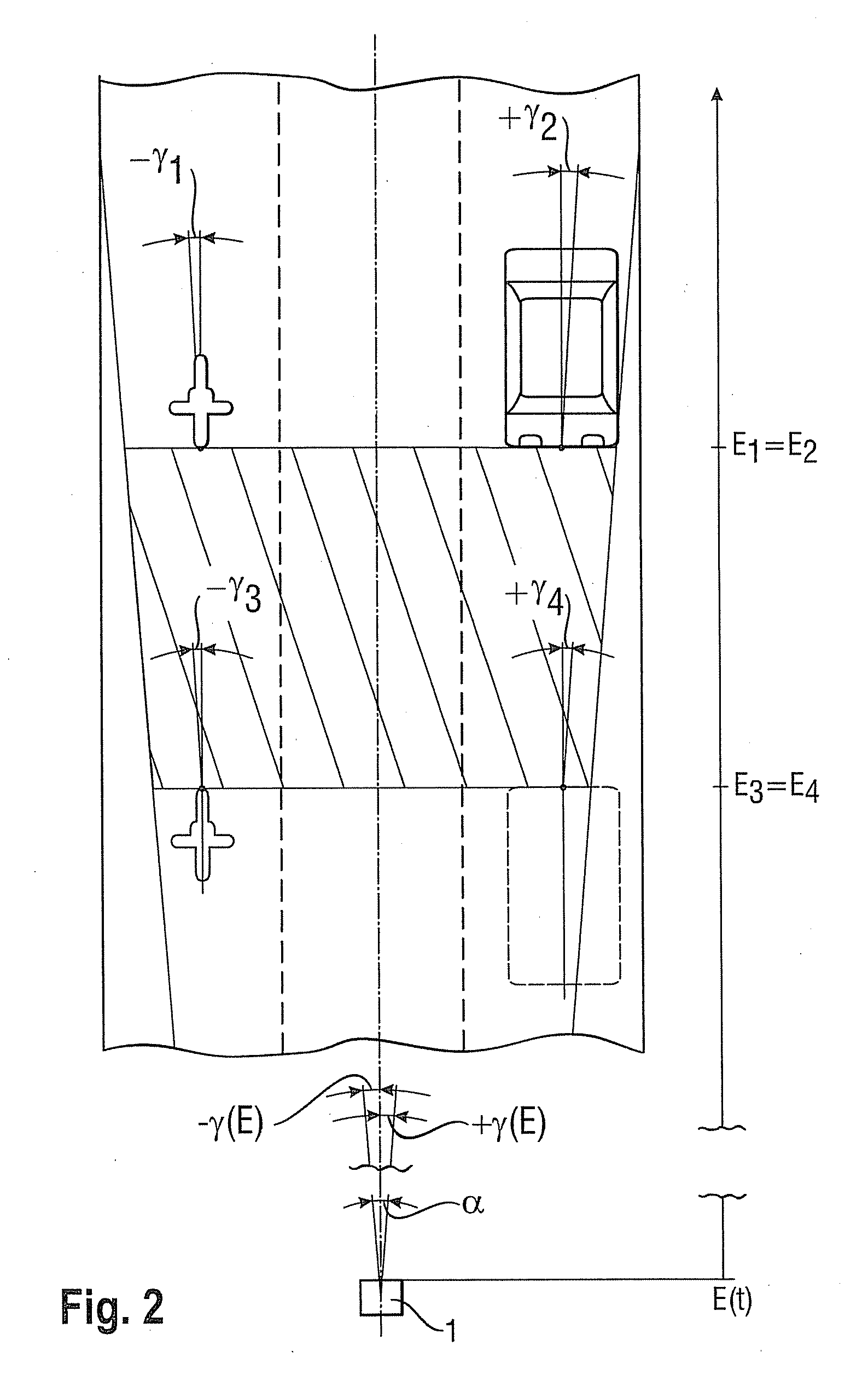
[0024]According to a second practical example, the radar system 1 could also be positioned above the road, e.g., on a bridge, as illustrated in FIG. 2, in which case, from a horizontal point of view, the radar axis coincides with the direction of the road.

[0025]These two fundamentally different configurations of the radar system 1 have hardly any effect on the measurement of the speed by means of the Doppler principle but differ considerably with respect to the possibility of identifying a vehicle based on its radial distance E from the radar system 1.

[0026]In the cas...


PUM


Abstract

A method of measuring the speed of a vehicle wherein the speed and the distance of the vehicle from a radar system and/or the measuring angle of the vehicle relative to the radar axis is determined by means of a radar measurement so as to characterize or determine the vehicle lane of the vehicle by means of the distance and/or the measuring angle. Knowledge of the vehicle lane makes it possible to unequivocally identify the detected vehicle in a group of vehicles unequivocally.

Description

FIELD OF THE INVENTION [0001]The present invention relates to a method of detecting the speed of a vehicle and of verifiably linking the speed measured to the detected vehicle, as generically disclosed in the Patent Specification EP 0 935 764 B1.BACKGROUND OF THE INVENTION [0002]Doppler radar systems are the principal measuring instruments used to control and enforce legal speed limits for vehicles.[0003]For such instruments to be approved for the intended use, it must be ensured and demonstrated that the speed measured is correct, on the one hand, and it must be possible to link the speed measured beyond doubt to the detected vehicle, on the other hand.[0004]The present invention relates to a method which solves, in particular, the problem of establishing such a link beyond doubt but which, in this context, also makes the speed measured plausible.[0005]The fact that there are measuring situations in which it is not possible to link, beyond doubt, the speed measured to the detected ...

Claims


Application Information

Patent Timeline
Patent Type & Authority Applications(United States)
IPC IPC(8): G01S13/58
CPCG01S13/42G01S13/584G01S13/92G08G1/04G08G1/054
Inventor KLEIN, CHRISTOPHBEHRENS, ANDREASDOHMANN, BERNHARDTERLAU, NORBERT
Owner JENOPTIK ROBOT GMBH
Why Eureka
Try Eureka