Recording apparatus

Inactive Publication Date: 2008-11-13
CANON KK
View PDF7 Cites 14 Cited by
  • Summary
  • Abstract
  • Description
  • Claims
  • Application Information

AI Technical Summary

Benefits of technology

[0013]The present invention provides a recording apparatus that allows a recording medium to make a U-turn and to be redirected, and that can restrict scratching of a recording surface of the recording medium when the recording medium and a conveying path contact each other. The present invention also provides a recording apparatus which can maintain recording speed due to continuous conveyance of recording media, and which can downsize a conveying mechanism.

Problems solved by technology

The coat layer on the recording surface is easily scratched when it comes into contact with a guide surface while the recording medium is being conveyed.
Therefore, the recording surface of the thick photo sheet tends to be more frequently scratched.
Therefore, work efficiency when recording media are loaded into the sheet feeding section is reduced, thereby reducing operational performance.
However, for widening the opening, the scanner needs to be moved towards the front, thereby increasing the depth of the apparatus.
Therefore, the recording surfaces come into contact with a conveying guide surface, and tend to be scratched.
As a result, the recording surface of the thick photo sheet is caused to more strongly contact the conveying guide surface, thereby making it more difficult to prevent the thick photo sheet from being scratched when the sheet is being conveyed.
Accordingly, it is difficult to convey all of the recording media by the U-turn sheet feeding operation.
However, in this structure, since the feeding and the ejection of the recording media are performed in the same conveying path, a mechanism that switches the conveying path is required, thereby causing the conveying mechanism to become complex.
In addition, a recording medium can only be fed after completing the ejection of a preceding recording medium.
Therefore, the recording media cannot be continuously conveyed.
As a result, the recording time cannot be reduced.
However, in this structure, the recording media cannot be continuously conveyed, as a result of which recording time cannot be reduced.
Therefore, the depth of the main body of the apparatus becomes large.
Further, since the recording sheet is redirected in the conveying path that is provided separately from the other conveying paths, conveying mechanical sections cannot be made common, thereby complicating the structure and increasing costs.

Method used


Image

  • Recording apparatus
  • Recording apparatus
  • Recording apparatus

Examples


first exemplary embodiment

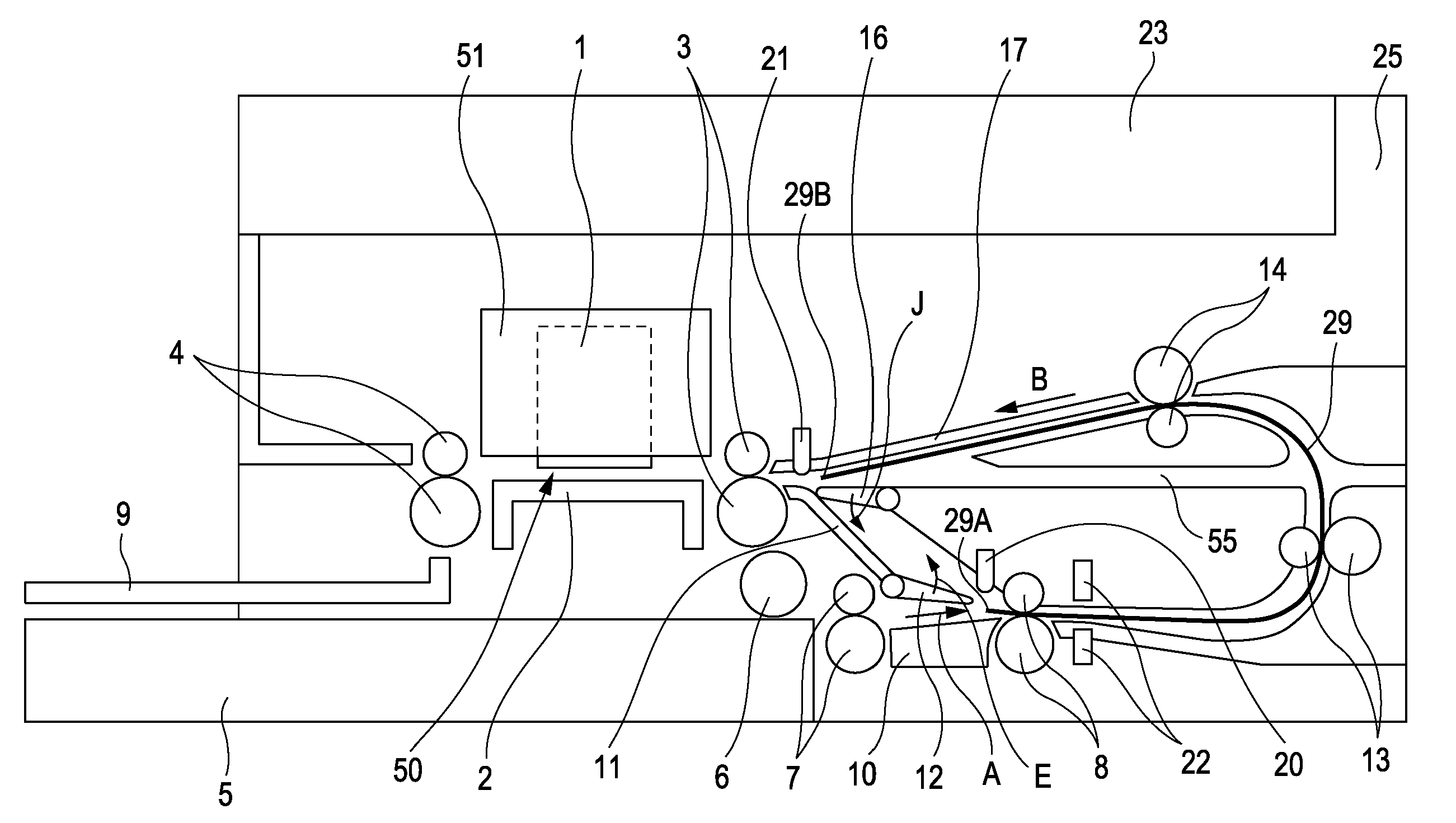
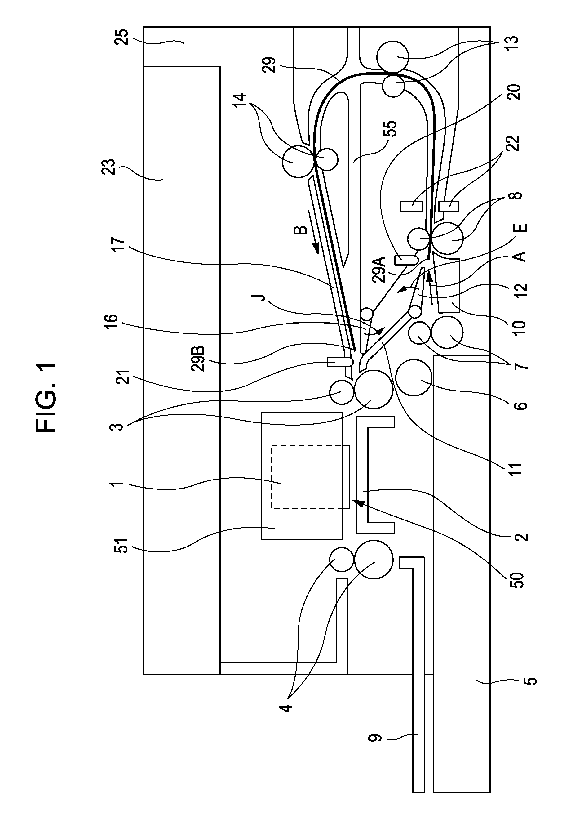
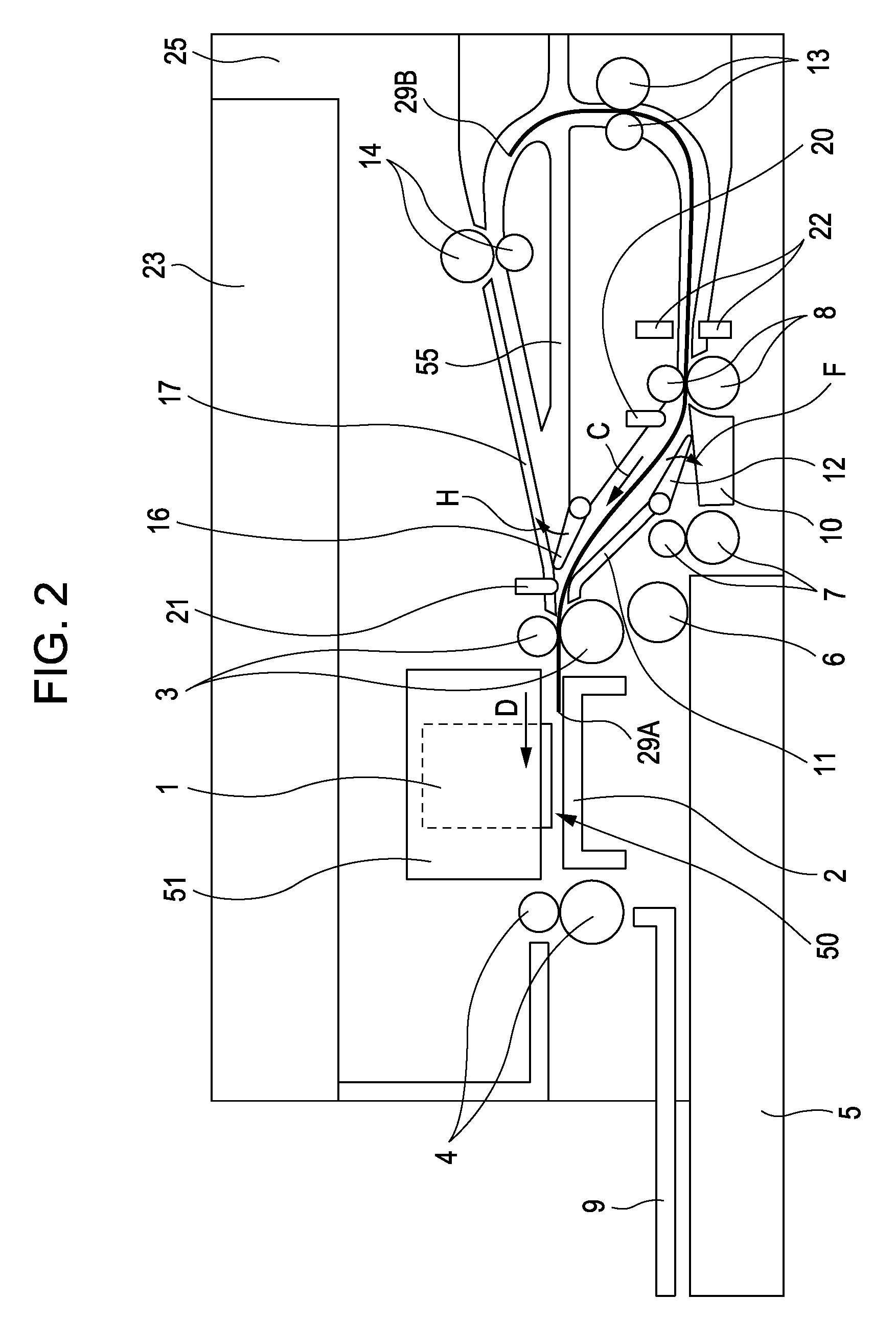
[0033]Exemplary embodiments of the present invention will now be described in detail below with reference to the drawings. Throughout the figures, the same reference numerals refer to the same or corresponding parts. FIGS. 1 to 8 are vertical sectional views of a recording apparatus according to a first exemplary embodiment of the present invention. FIG. 1 shows a state after a special sheet is conveyed and just before the special sheet is redirected. FIG. 2 shows a state when the special sheet is redirected. FIG. 3 illustrates a state when an ordinary sheet makes a U-turn, and a state when a recording medium having a high rigidity reciprocates along a horizontal conveying path. FIG. 4 shows a state in which, for performing a duplex recording operation, a recording medium having one side recorded is reversely conveyed to introduce the recording medium to a U-turn conveying path. FIG. 5 shows a state when the recording medium is conveyed along the U-turn conveying path from the state...

second exemplary embodiment

[0050]FIG. 9 is a vertical sectional view showing a state just before a recording medium is redirected in a recording apparatus according to a second exemplary embodiment of the present invention. FIG. 10 is a vertical sectional view showing a state when the recording medium is redirected. FIG. 11 is a vertical sectional view showing a state in which, for performing a duplex recording operation, a recording medium having one side recorded is reversely conveyed to introduce the recording medium to a U-turn conveying path. FIG. 12 is a vertical sectional view showing a state when the recording medium is conveyed along the U-turn conveying path to start recording of an image on the recording medium at an image forming portion. FIG. 13 is a vertical sectional view showing a state in which a preceding recording medium during continuous conveyance is redirected to perform a recording operation. FIG. 14 is a vertical sectional view showing a state just before starting redirection of a next...

third exemplary embodiment

[0060]FIG. 15 is a vertical sectional view of a structure of and a conveying operation in a conveying path of a recording apparatus according to a third exemplary embodiment of the present invention. In the second exemplary embodiment, the redirecting conveying path is formed by a conveying path having an opening 25A at the upper portion of the main body of the apparatus. In contrast, in the third exemplary embodiment, a redirecting conveying path is formed in a main body 25 of the apparatus so as to be disposed between an image forming portion 50 and a scanner 23. When a recording medium is pulled in for being redirected, the recording medium that is fed from a sheet feeding cassette 5 is conveyed from the direction of arrow A to the direction of arrow P. Then, the recording medium is conveyed to a conveying path 26 formed between the image forming portion 50 and the scanner 23. The conveying path 26 constitutes part of the redirecting conveying path.

[0061]That is, after the record...


PUM


Abstract

A recording apparatus that forms an image on a recording medium includes a U-turn conveying path and a redirecting conveying path. The U-turn conveying path reverses the front and back of the recording medium and conveys the recording medium to a conveying roller. The redirecting conveying path reverses a conveying direction of the recording medium, fed from the front side of a main body of the apparatus, at an upstream side of the conveying roller in the conveying direction, and conveys the recording medium to the conveying roller. Then, a first recording medium is conveyed along the U-turn conveying path, and a second recording medium is conveyed along the redirecting conveying path.

Description

BACKGROUND OF THE INVENTION[0001]1. Field of the Invention[0002]The present invention relates to a recording apparatus that forms an image onto a recording medium, which is conveyed by a conveying roller, by using a recording head. More particularly, the present invention relates to a novel recording apparatus having a conveying path.[0003]2. Description of the Related Art[0004]In a recording apparatus that forms an image onto a recording medium by using a recording head, a recording medium that is fed from a sheet feeding unit is conveyed to an image forming section by a conveying roller. Then, an image is formed onto the recording medium that is conveyed through the image forming section. A recording apparatus including, as a conveying mechanism of a recording apparatus, a duplex recording conveying mechanism instead of a conveying mechanism that conveys a recording medium that is supplied from the back side of the apparatus is available. The duplex recording conveying mechanism c...

Claims


Application Information

Patent Timeline
IPC IPC(8): G01D15/00
CPCB41J3/60
Inventor UCHIDA, HARUO
Owner CANON KK
Why Eureka
Try Eureka