
Imaging device

a technology of imaging device and image, which is applied in the field of imaging device, can solve the problems of insufficient resolution of an image displayed on the evf in many cases, and it is difficult for a photographer to achieve a highly precise focus

Inactive Publication Date: 2008-11-13
OLYMPUS CORP
View PDF10 Cites 13 Cited by
  • Summary
  • Abstract
  • Description
  • Claims
  • Application Information

AI Technical Summary

Benefits of technology

The patent describes an imaging device that can display a focused area on a screen and adjust the focus. However, the resolution of the image displayed on the EVF is often insufficient compared to the video signal output from the device. The patent aims to provide a function to assist focus adjustment while avoiding troublesome operations for the photographer. The device detects physical movement of the optical focusing portion and automatically converts the focused area of the image signal into a preset number of pixels for display on the screen. This allows for easier focus adjustment and ensures that the image looks natural to the photographer.

Problems solved by technology

However, the resolution of an image displayed on the EVF is insufficient in many cases in comparison with a video signal output from the imaging device or an image signal recorded on the imaging device.
Therefore, it is difficult for a photographer to attain a highly precise focus while watching the display of the EVF.

Method used


Image

  • Imaging device
  • Imaging device
  • Imaging device

Examples


first embodiment

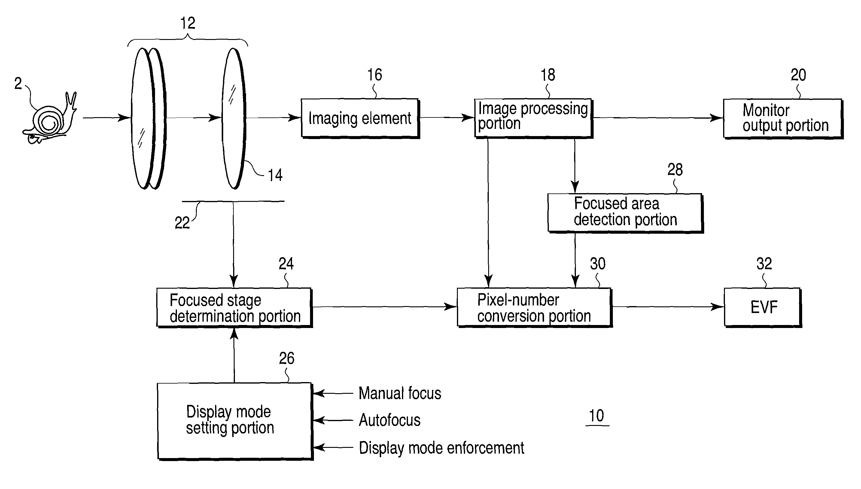
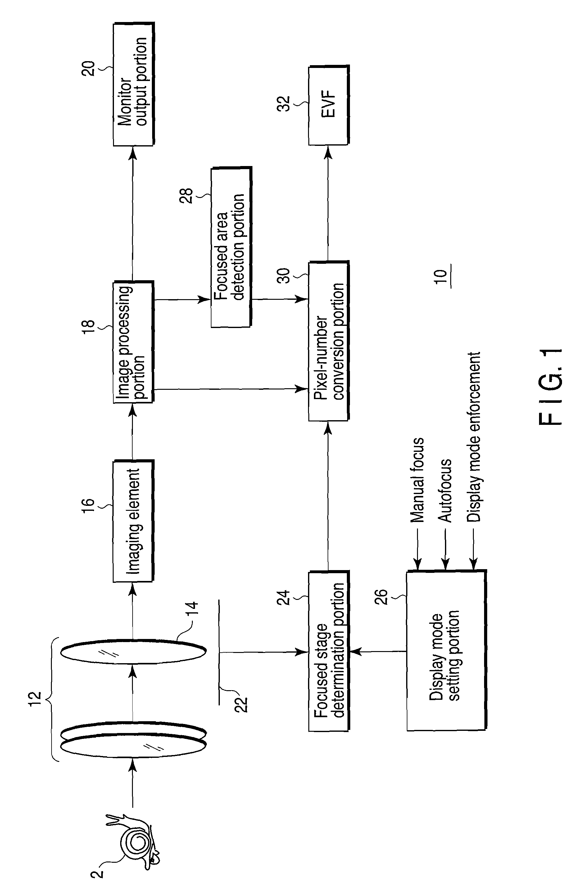
[0025]FIG. 1 is a block diagram showing the configuration of an imaging device according to a first embodiment of this invention.

[0026]In FIG. 1, the imaging device is configured by a lens group (optical focusing portion) 12 containing focus lenses 14 to input a subject 2 as an optical image to an imaging element, an imaging element 16 that converts an optical image into an imaging signal, an image processing portion 18 that generates an image signal from the imaging signal, a pixel-number conversion portion 30 that converts at least a partial area of the image signal into a pixel number to be input to an EVF (image display portion) 32, a focused area detection portion 28 that detects a focused area based on the high-frequency component of the image signal and selects or extracts the focused area, a focus lens movement detector (focusing portion detector) 22 that detects the movement of the focus lenses 14, a focused stage determination portion 24 that determines a focus adjustment ...

second embodiment

[0062]Next, one example in which an imaging device of this invention is applied to an imaging device of an interchangeable EVF system is explained with reference to FIG. 8 as a second embodiment of this invention.

[0063]In this case, since the basic configuration of the imaging device is the same as the first embodiment described before in the second embodiment as will be described below, the same reference numbers are attached to the same portions and the indication in the drawings and the explanation thereof are omitted in order to avoid the repeated explanation and only different portions are explained.

[0064]An EVF 32 shown in FIG. 8 is detachably attached to the main body of an imaging device 60. The EVF 32 may be in conformity with one of the standards of HD-SDI, NTSC, PAL or can be connected to the main body of the imaging device even in a case wherein the scanning line is 1080i or 1080p or may be a nonstandard EVF. Further, the configuration of a display portion of the EVF 32 ...


PUM


Abstract

In a present imaging device, an optical image formed through a lens group from a subject is converted into an imaging signal by an imaging element and a focused area is detected by a focused area detection portion. Optical displacement or physical movement of the lens group is detected by a focus lens movement detector and an adjustment stage of the lens group is determined by a focused stage determination portion based on a detection signal output from this. Based on the determination result, the focused area of the imaging signal is automatically enlarged and output.

Description

CROSS-REFERENCE TO RELATED APPLICATIONS[0001]This is a Continuation Application of PCT Application No. PCT / JP2007 / 071056, filed Oct. 29, 2007, which was published under PCT Article 21(2) in Japanese.[0002]This application is based upon and claims the benefit of priority from prior Japanese Patent Application No. 2006-301935, filed Nov. 7, 2006, the entire contents of which are incorporated herein by reference.BACKGROUND OF THE INVENTION[0003]1. Field of the Invention[0004]This invention relates to an imaging device and more particularly to an imaging device that converts a focused area of an image signal into a preset number of pixels and displays an image.[0005]2. Description of the Related Art[0006]The technique associated with a moving body tracking device in which a signal of a specified area of a photoelectric conversion element is read and the specified area is displayed on a display circuit based on a specified area specifying signal from an area specifying circuit by use of ...

Claims


Application Information

Patent Timeline
Patent Type & Authority Applications(United States)
IPC IPC(8): H04N5/232H04N23/40
CPCG02B7/365G03B13/36G03B15/16H04N5/23212H04N5/23293H04N23/673H04N23/635
Inventor OTSU, HIRONAO
Owner OLYMPUS CORP
Learn More