Perpendicular magnetic recording head

a magnetic recording head and perpendicular technology, applied in the field of perpendicular magnetic recording head, can solve the problems of increasing the magnetic field applied to the recording medium, unable to obtain sufficient side fringing suppressing effect, and deteriorating total recording performance, so as to reduce the intensity of recording magnetic field, enhance the side shield effect, and suppress side fringing

Active Publication Date: 2008-11-13
TDK CORPARATION
View PDF5 Cites 9 Cited by
  • Summary
  • Abstract
  • Description
  • Claims
  • Application Information

AI Technical Summary

Benefits of technology

[0009]It is an object of the present invention to provide a perpendicular magnetic recording head which can suppress side fringing while keeping the recording magnetic field intensity from decreasing.
[0010]The present invention is achieved by taking account of the facts that a side shield effect can be enhanced when providing a pair of side shield layers on both sid...

Problems solved by technology

This causes a fear of recording actions failing for recording media having a high coercivity, whereby the total recording performance will deteriorate even if the recording magnetic field gradient improves.
Therefore, a sufficient side fringing suppressing ef...

Method used


Image

  • Perpendicular magnetic recording head
  • Perpendicular magnetic recording head
  • Perpendicular magnetic recording head

Examples


first embodiment

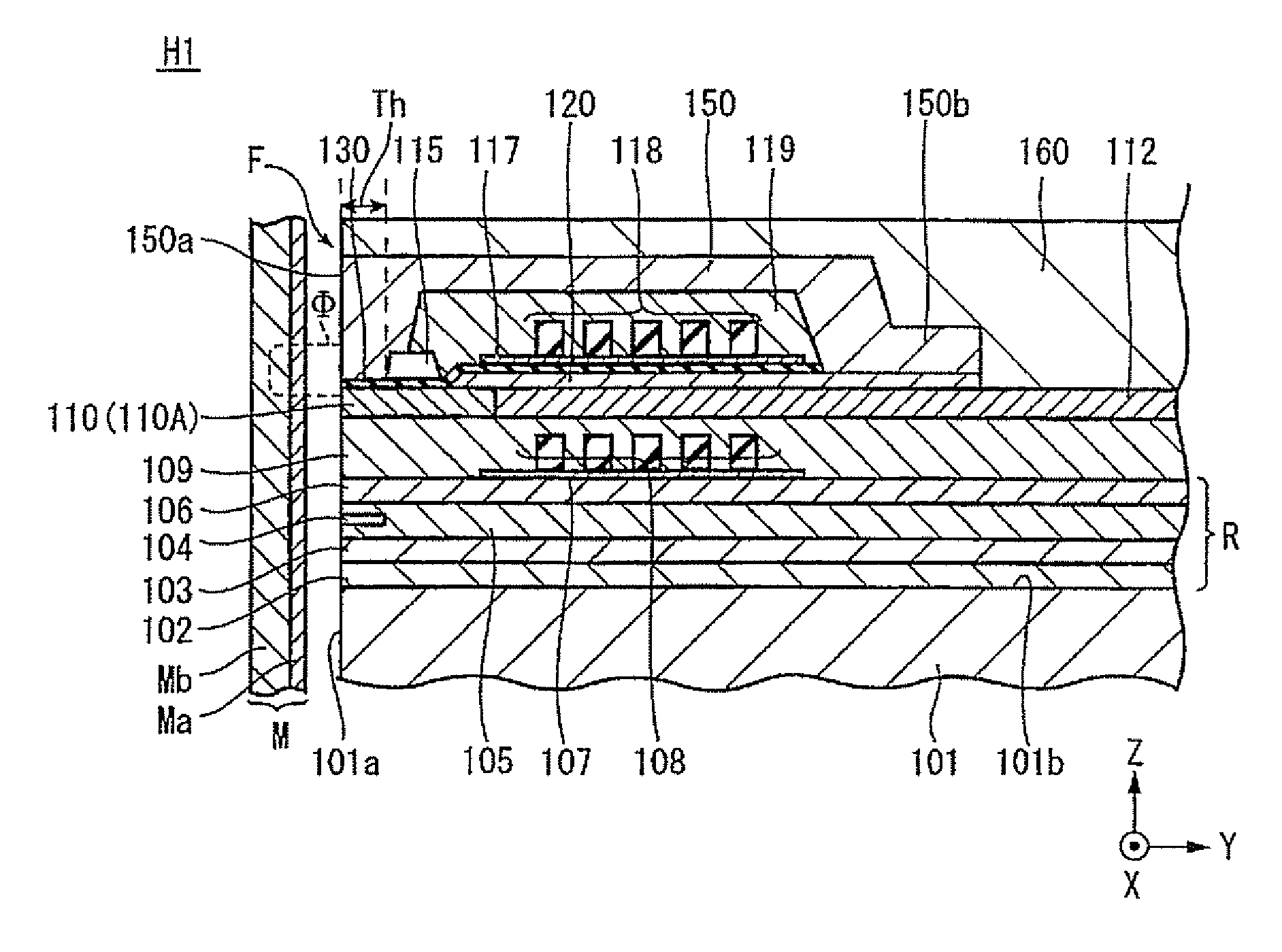
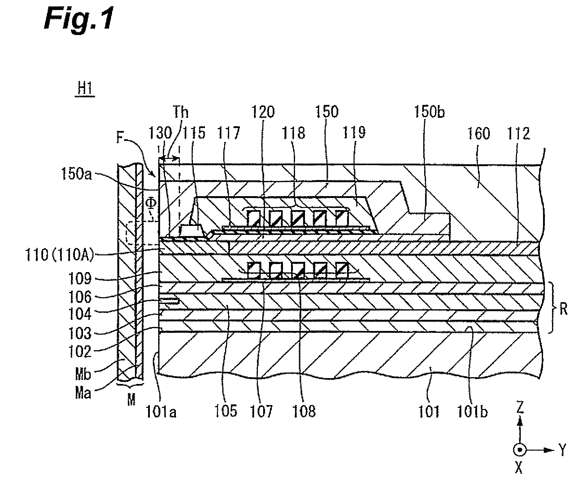
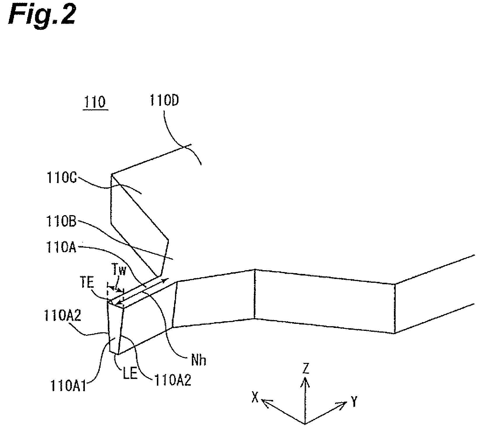
[0025]FIG. 1 is a vertical sectional view showing the multilayer structure of the perpendicular magnetic recording head H1 in accordance with the present invention, while FIG. 2 is a perspective view for explaining a main magnetic pole form.

[0026]The perpendicular magnetic recording head H1 provides a recording medium M with a recording magnetic flux Φ perpendicular thereto, thereby perpendicularly magnetizing a hard film Ma of the recording medium M. The recording medium M has the hard film Ma with a higher remanent magnetization on the medium surface side and a soft film Mb with a higher magnetic permeability on the inner side of the hard film Ma. The recording medium M is shaped like a disk, for example, and is rotated about the center of the disk as a rotary axis. A slider 101 is formed by a nonmagnetic material such as Al2O3.TiC. The slider 101 has a medium-opposing surface 101a opposing the recording medium M. As the recording medium M rotates, a surface airflow levitates the ...

second embodiment

[0065]The foregoing steps yield the pair of side shield layers 200, magnetic gap layer 130, and return yoke layer 150 shown in FIG. 5. In the second embodiment, the part of side shield layers 200 positioned directly below the part of magnetic gap layer 130 outside of the gap width Wg is removed together with the latter in the etching step for defining the gap width Wg of the magnetic gap layer 130, whereby the size of the pair of side shield layers 200 in the track width direction is determined according to the gap width Wg.

[0066]FIGS. 7 and 8 show a third embodiment of the present invention. FIG. 7 is a transverse sectional view showing the multilayer structure of a perpendicular magnetic recording head H3 as seen from the medium-opposing surface side. The third embodiment is a modified example of the above-mentioned first embodiment in which an auxiliary magnetic gap layer 140 interposed between the return yoke layer 150 and a pair of side shield layers 200 is provided in the rema...

third embodiment

[0068]The auxiliary magnetic gap layer 140 has such a thickness d2 as to generate a magnetic connection between the return yoke layer 150 and the pair of side shield layers 200. Here, the magnetic connection refers to a state where a leakage magnetic flux occurs between the return yoke layer 150 and the pair of side shield layers 200 through a connection weaker than a direct connection between the return yoke layer 150 and the pair of side shield layers 200. Specifically, it will be desirable if the thickness d2 of the auxiliary magnetic gap layer 140 is about 30 to 50 nm. The magnetic gap distance is defined by the thickness Tg in the third embodiment as well.

[0069]Since the pair of side shield layers 200 are separated from the return yoke layer 150 by the magnetic gap layer 130 and auxiliary magnetic gap layer 140 in the vicinity of the main magnetic pole layer 110 (partial area α), recording magnetic fluxes directed from the main magnetic pole layer 110 to the recording medium M ...


PUM


Abstract

To provide a perpendicular magnetic recording head which can suppress side fringing while keeping the recording magnetic field intensity from decreasing.
In a perpendicular magnetic recording head comprising a main magnetic pole layer and a return yoke layer which are laminated with a magnetic gap layer interposed therebetween on a medium-opposing surface, and a pair of side shield layers positioned on both sides in the track width direction of the main magnetic pole layer while interposing a nonmagnetic material layer therebetween, the magnetic gap layer is formed in a partial area in the track width direction bridging the main magnetic pole layer and the pair of side shield layers. The pair of side shield layers are in contact with the return yoke layer in a remaining area where the magnetic gap layer is absent.

Description

BACKGROUND OF THE INVENTION[0001]1. Field of the Invention[0002]The present invention relates to a perpendicular magnetic recording head which performs a recording action by applying a recording magnetic field perpendicularly to a recording medium plane.[0003]2. Related Background Art[0004]As is well-known, a perpendicular magnetic recording head includes a main magnetic pole layer and a return yoke layer which have front end faces exposed at a surface opposing a recording medium (medium-opposing surface) and are magnetically coupled to each other on the deeper side of the medium-opposing surface in the height direction, a magnetic gap layer interposed between the main magnetic pole layer and return yoke layer on the medium-opposing surface, and a coil layer inducing a recording magnetic field between the main magnetic pole layer and return yoke layer upon energization. The recording magnetic field induced between the main magnetic pole layer and return yoke layer perpendicularly en...

Claims


Application Information

Patent Timeline
IPC IPC(8): G11B5/23
CPCG11B5/1278G11B5/3116G11B5/315
Inventor KAMEDA, HIROSHIKOBAYASHI, KIYOSHI
Owner TDK CORPARATION
Why Eureka
Try Eureka