Mold-Concrete Composite Crossbeam and Construction Method Using the Same

a technology of composite crossbeams and crossbeams, which is applied in the direction of building components, building repairs, structural elements, etc., can solve the problems of weak h-steel against fire, structural damage, and structural damage, and achieve the effect of reducing the height of the slab structure and reducing the height of the story

Inactive Publication Date: 2008-11-20
KH HOUSING SOLUTIONS
View PDF1 Cites 35 Cited by
  • Summary
  • Abstract
  • Description
  • Claims
  • Application Information

AI Technical Summary

Benefits of technology

[0012]The present invention is designed in consideration of the above problems, and therefore it is an object of the invention to provide a mold-concrete composite crossbeam capable of effectively reducing the height of story by decreasing the height of a slab structure without causing any bad influence on the safety of a building.

Problems solved by technology

However, the slab structure 19 is disadvantageous in that a process for welding the stand 16 to the web 12b is additionally required, and the structure may have seriously bad stability if the welding portion between the stand 16 and the web 12b is not firm.
In addition, in the above slab structures, H-steel is weak against fire since it is exposed outward.
That is to say, high temperature caused by the fire may be directly transferred to the H-steel, which may cause deformation of the H-steel.
Thus, it causes delay of construction process and economic loss in installing the mold and also removing the mold after casting.

Method used


Image

  • Mold-Concrete Composite Crossbeam and Construction Method Using the Same
  • Mold-Concrete Composite Crossbeam and Construction Method Using the Same
  • Mold-Concrete Composite Crossbeam and Construction Method Using the Same

Examples


Embodiment Construction

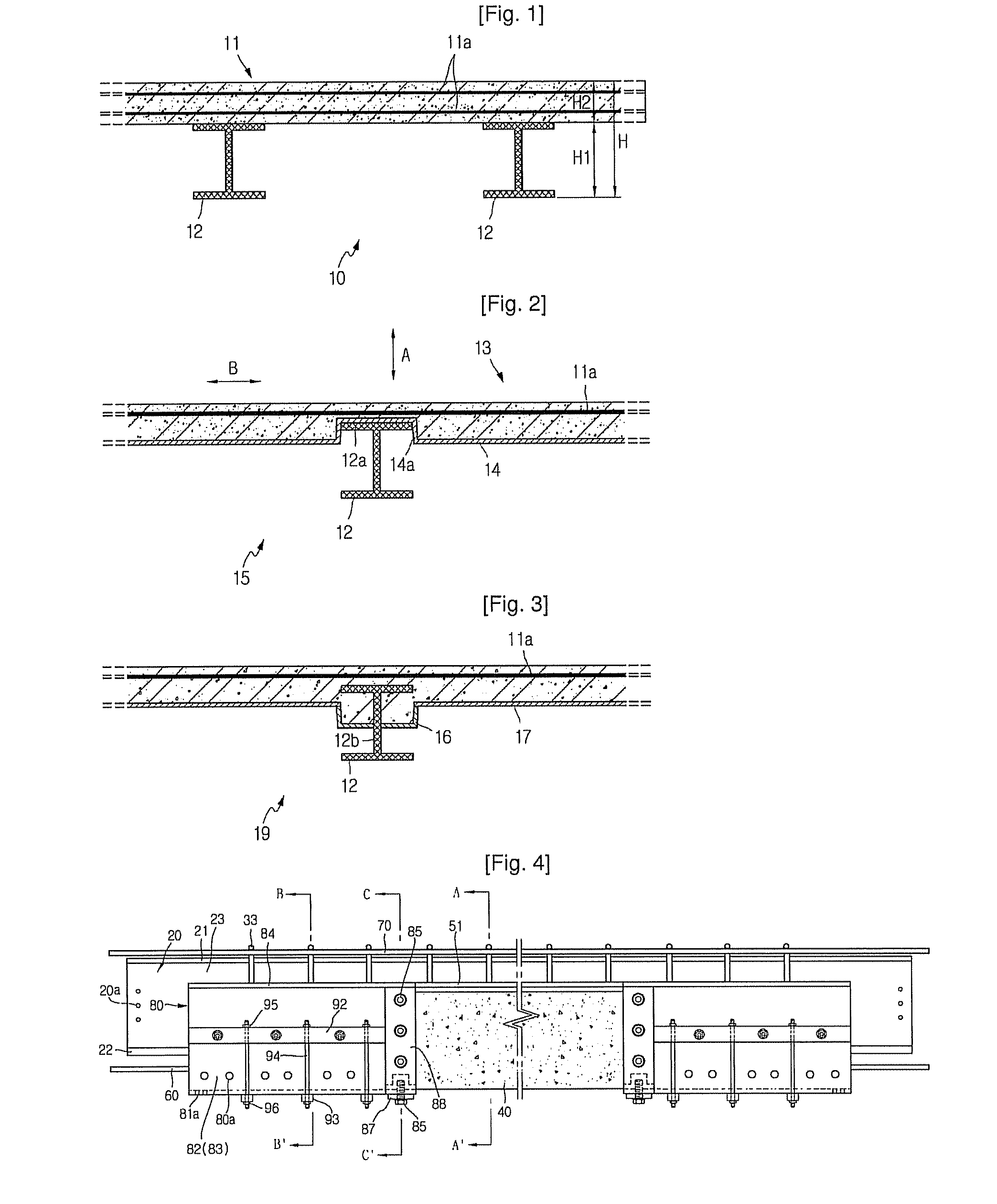
[0060]FIG. 4 is a side view showing a mold-concrete composite crossbeam according to a preferred embodiment of the present invention.

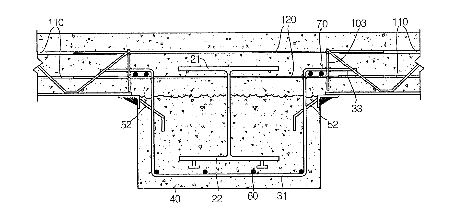
[0061]Referring to FIG. 4, the mold-concrete composite crossbeam of the present invention includes a H-steel 20, reinforcing steel bars installed around the H-steel 20 in its length direction, a concrete member 40, and molds 80 detachably installed to both ends of the concrete member 40.

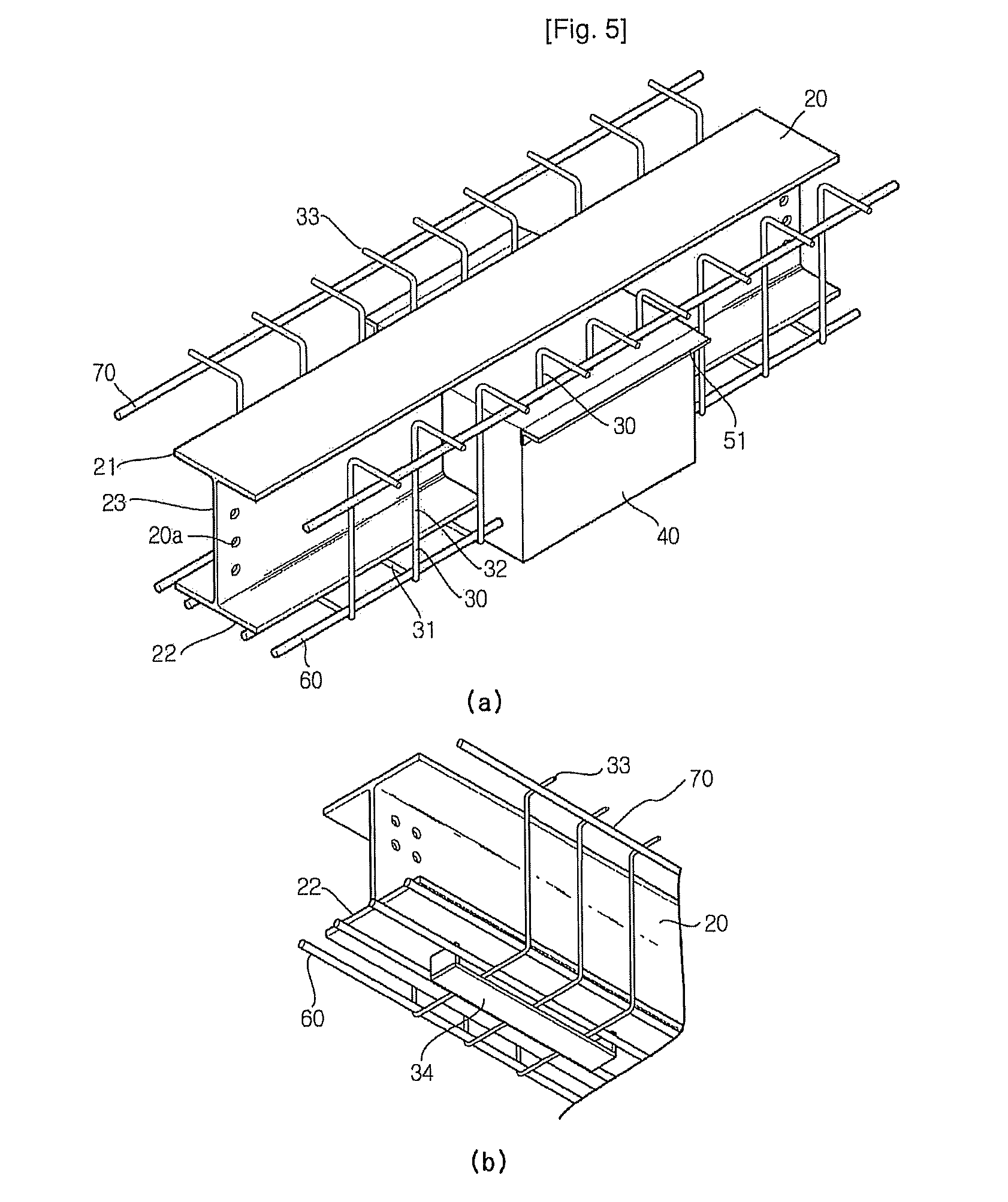
[0062]FIGS. 5a and 5b schematically show only the concrete crossbeam of the mold-concrete of FIG. 4 except the mold, FIG. 6 is a sectional view taken along the line A-A′ of FIG. 4, FIG. 7 is a sectional view taken along the line B-B′ of FIG. 4, and FIG. 8 is a sectional view taken along the line C-C′ of FIG. 4. Referring to FIGS. 5a to 8 together, the H-steel 20 is composed of an upper flange 21 and a lower flange 22 arranged in parallel, and a web 23 for interconnecting the upper and lower flanges 21, 22.

[0063]Preferably, a stud 22a buried in the concrete member 40 may...


PUM


Abstract

A mold-concrete composite crossbeam includes a H-steel composed of upper and lower flanges and a web connecting them; a concrete member formed in a length direction of the H-steel to expose the upper flange out but bury the lower flange and the web partially; deck plate supports installed to both upper side edges of the concrete member to support a deck plate placed thereon; a reinforcing steel bar installed around the H-steel; a mold including a bottom detachably coupled to a lower end surface of the concrete member, and sidewalls formed in parallel to both sides of the bottom and detachably coupled to both end sides of the concrete member; a lateral reinforcing member coupled across both sidewalls; a side reinforcing member installed to an outer side of the sidewalls in a length direction; and bottom reinforcing members installed across a lower surface of the bottom.

Description

TECHNICAL FIELD[0001]The present invention relates to a mold-concrete composite crossbeam, and more particularly to a mold-concrete composite crossbeam capable of effectively resisting a bending moment and a compressive stress and integrally provided with a mold to effectively place concrete. The present invention also relates to a construction method using such a mold-concrete composite crossbeam.BACKGROUND ART[0002]Generally, a H-steel crossbeam is widely used for supporting floor or slab acting as the ceiling of each story of a building. That is to say, as shown in FIG. 1, a H-steel crossbeam 12 and a slab 11 configure a slab structure 10.[0003]Meanwhile, the height of each story of the building is equal to the sum of the height of a room space and the height of the slab structure 10. That is to say, as the height of the slab structure 10 is reduced, the height of each story may be decreased. Thus, as the height of the slab structure 10 is small, the height of a story is reduced ...

Claims


Application Information

Patent Timeline
Patent Type & Authority Applications(United States)
IPC IPC(8): E04C3/293
CPCE04C3/293E04B5/23E04C5/06E04B1/30
Inventor HONG, WON-KEEHWANG, KI-SOO
Owner KH HOUSING SOLUTIONS
Why Eureka
Try Eureka