
Forced air furnace

a forced air furnace and furnace technology, applied in the field of forced air furnaces, can solve the problems of inability to the length and complexity of the ductwork vary considerably, and the furnace cannot meet the ideal flow rate of a building, so as to overcome or mitigate one or more disadvantages.

Inactive Publication Date: 2008-11-20
STELPRO DESIGN
View PDF11 Cites 11 Cited by
  • Summary
  • Abstract
  • Description
  • Claims
  • Application Information

AI Technical Summary

Benefits of technology

[0005]It is an object of the present invention to provide a forced air furnace that overcomes or mitigates one or more disadvantages of known forced air furnaces, or at least provides a useful alternative.

Problems solved by technology

The length and complexity of these ductworks vary considerably depending on the building requirements.
However, it may happen that the ideal flow rate in a building, considering air speed and temperature difference, may not be available from the forced air furnace.
Because of this limited adjustment capability, some forced air furnace installations are less than ideal.
Indeed, the forced air furnace may provide too little or too much air in the rooms, the air may be coming in the room too fast or not warm enough, etc.
In the end, the lack of possibilities of conventional forced air furnaces generates a lack of comfort for the building occupants.
Further to not having a properly calibrated air heating system in some installations, situations may arise where, at a required fan motor speed, the fan motor is either too lightly or too much loaded, drawing much current and approaching its maximum recommended operating amperage.
In these situations, the fan motor operates outside its ideal operating range, which may be detrimental to its durability.
Furthermore, because more current is drawn by the fan motor, energy cost is higher.

Method used


Image

  • Forced air furnace
  • Forced air furnace
  • Forced air furnace

Examples


Embodiment Construction

[0017]The forced air furnace of the present invention is provided with added adjustment mechanisms, allowing better tailoring of an airflow rate, airflow speed, air temperature and fan motor amperage. This added adjustability eventually translates to a better comfort for occupants of a building.

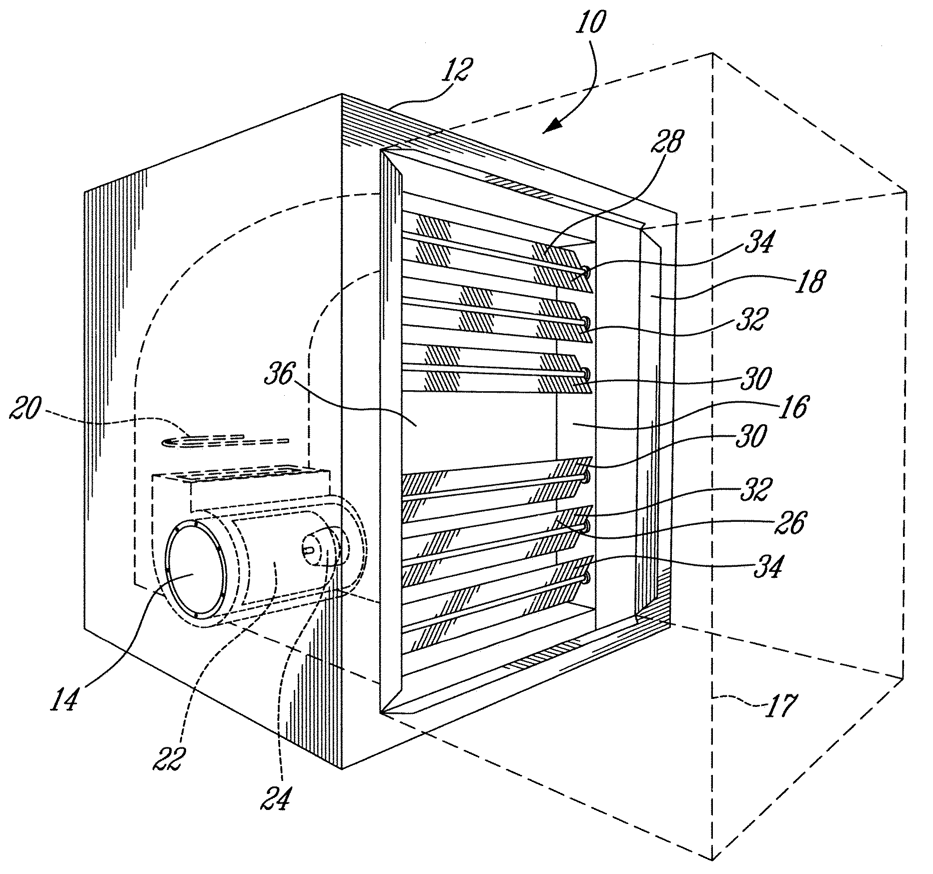
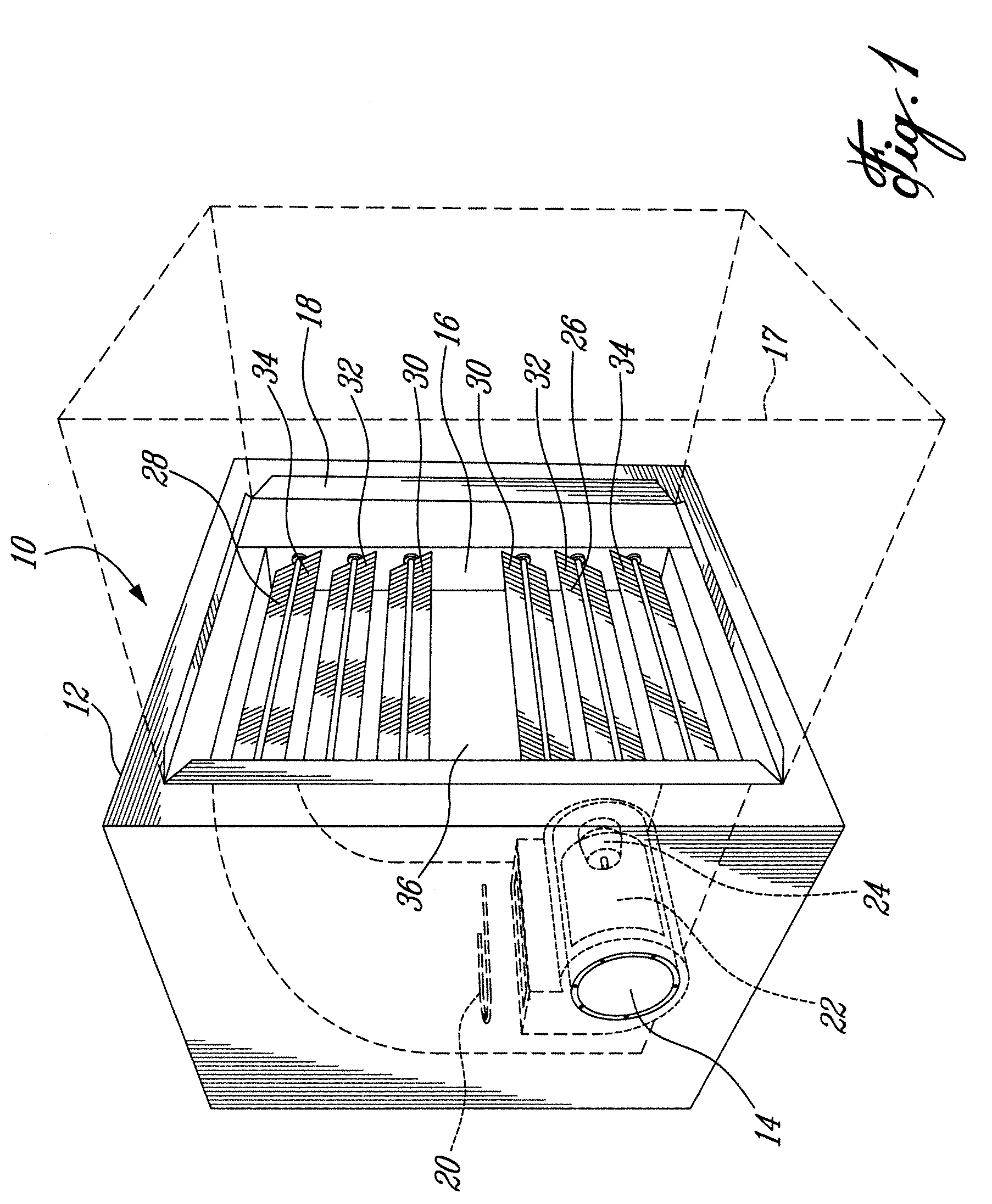
[0018]FIG. 1 generally depicts a forced air furnace 10. The forced air furnace 10 comprises an enclosure 12 in which an air inlet 14 and an air outlet 16 are provided. An interface 18 is also made in the enclosure 12, all around the air outlet 16. This interface 18 is used to connect the forced air furnace 10 to a duct 17, shown in dotted lines in this figure for clarity reasons. The enclosure 12 contains an electric heating element 20, such as a resisting element, and a fan 22 powered by its own electric fan motor 24. An outlet adjusting mechanism 26 is placed in the air outlet 16 to vary the effective size, or exhaust area, of the air outlet 16. This way, the outlet adjusting mechanism 26 i...


PUM


Abstract

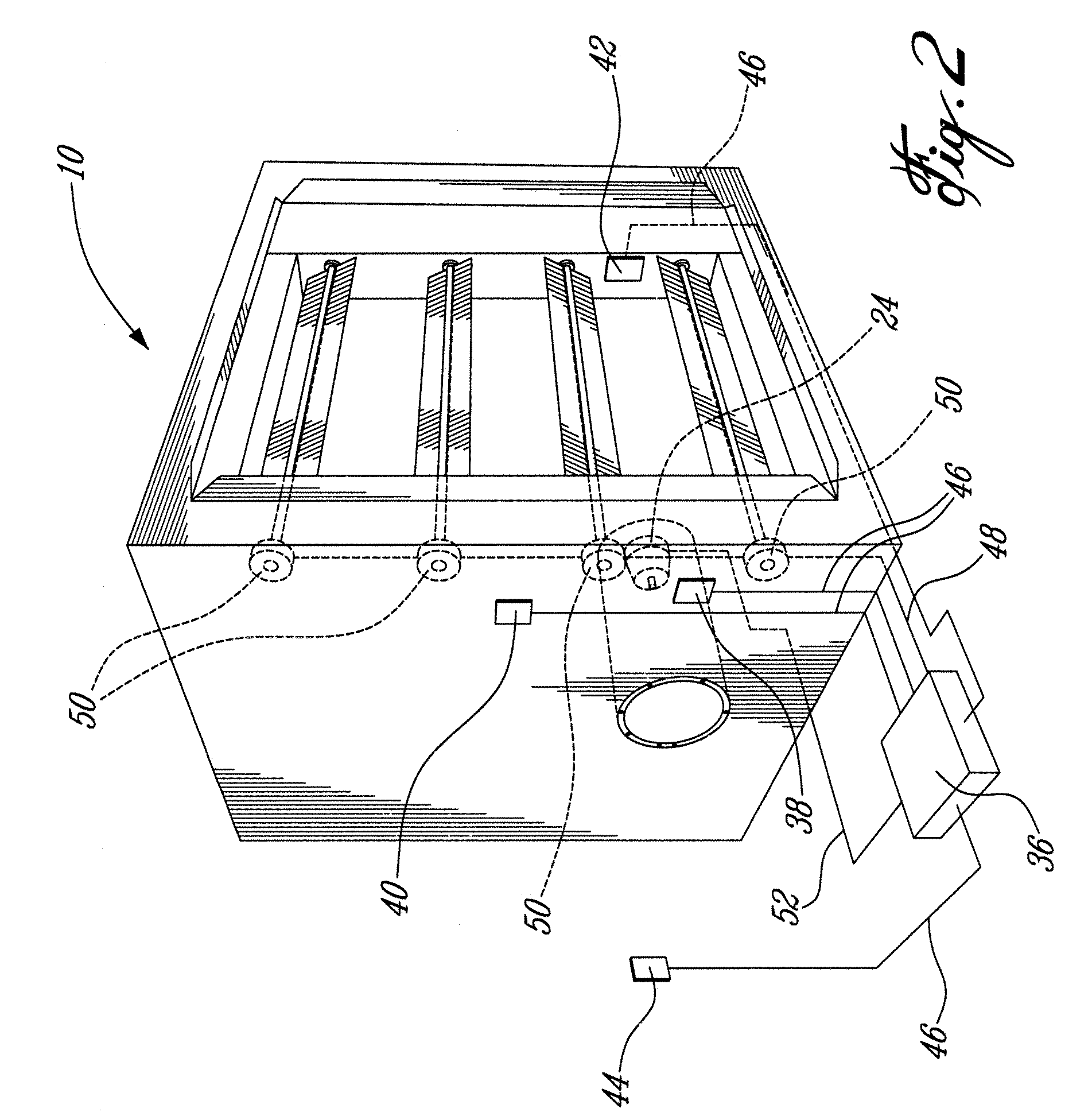
A forced air furnace comprises an enclosure, an adjusting mechanism, an interface, an electric heating element and a fan. The enclosure has an air inlet and an air outlet. The adjusting mechanism is operative to adjust the air outlet between an open position and a partially closed position. The interface is located proximate to the air outlet and is used to connect the air outlet to a duct. The fan is powered by an electric motor. Both the fan and the electric heating element are located inside the enclosure. There is also described a method of installing a forced air furnace. The method comprises the step of adjusting a size of an exhaust area of an air outlet of the forced air furnace in order to produce a desired exhaust airflow through the exhaust area when the forced air furnace is connected to a ductwork.

Description

FIELD OF THE INVENTION[0001]The present invention generally relates to the field of forced air furnaces. More specifically, the invention relates to a forced air furnace having an adjustable air outlet.BACKGROUND OF THE INVENTION[0002]Forced air furnaces are used both in residential homes and commercial buildings. These forced air furnaces are typically connected to a ductwork that conveys heated air to different rooms in the building. The length and complexity of these ductworks vary considerably depending on the building requirements.[0003]The forced air furnaces are designed such that, in operation, their internal pressure, airflow for a given motor speed, and airflow direction are fixed. Only the fan motor speed may be adjusted during installation. Indeed, depending on the ductwork, which provides a back pressure on the forced air furnace, the fan motor speed may require adjustment so that it is capable of pushing air at a required flow rate in all the rooms of the building. In ...

Claims


Application Information

Patent Timeline
Patent Type & Authority Applications(United States)
IPC IPC(8): F24H3/02
CPCF24H9/2071F24H15/238F24H15/281F24H15/20F24H15/204F24H15/33F24H15/421F24H15/176F24H15/242F24H15/35
Inventor MICHAUD, BERTRANDBRETON, RICHARD
Owner STELPRO DESIGN
Learn More