Computer mouse bearing personalized and replaceable graphical indicia

a computer mouse and indicia technology, applied in the field of computer mouse, can solve the problem that the visual indicia placed on the computer mouse cannot be readily changed, and achieve the effect of easy replacement and no or minimal additional cos

Inactive Publication Date: 2008-11-20
ROVERY RITA +1
View PDF17 Cites 5 Cited by
  • Summary
  • Abstract
  • Description
  • Claims
  • Application Information

AI Technical Summary

Benefits of technology

[0011]Briefly stated and in accordance with the preferred embodiment of the present invention, a computer mouse is described comprising a bottom surface movable on a flat surface, an upper surface comprising a switch actuator portion, and a distending portion between the bottom surface and the upper surface. In the first embodiment of the present invention, a detachable and transparent hand rest portion is provided that can be affixed to the upper surface of the computer mouse. Graphical material can be placed beneath this detachable and transparent hand rest portion so that it is visible to the user. In a second embodiment of the present invention, a computer mouse comprises a bottom surface movable on a flat surface, an upper surface comprising a hand rest portion and a switch actuator portion, a distending portion between the bottom surface and the upper surface, and a detachable transparent cover overlaying said hand rest portion wherein said cover is sized to be selectively snapped on and off said computer mouse and incorporates sufficient space between the hand rest portion and said cover to permit placement of graphical material. In both preferred embodiments, the graphical material can be readily replaced at no or minimal additional cost.

Problems solved by technology

One common shortcoming with each of the aforementioned prior art devices is that the visual indicia placed on the computer mouse cannot readily be changed.

Method used


Image

  • Computer mouse bearing personalized and replaceable graphical indicia
  • Computer mouse bearing personalized and replaceable graphical indicia
  • Computer mouse bearing personalized and replaceable graphical indicia

Examples


Embodiment Construction

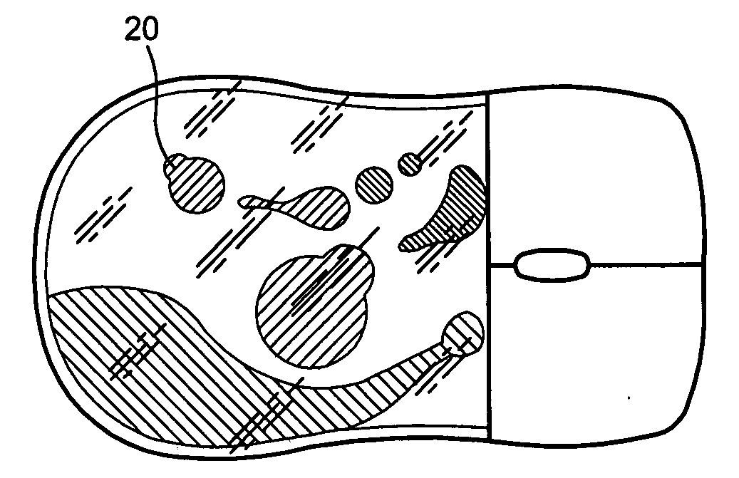
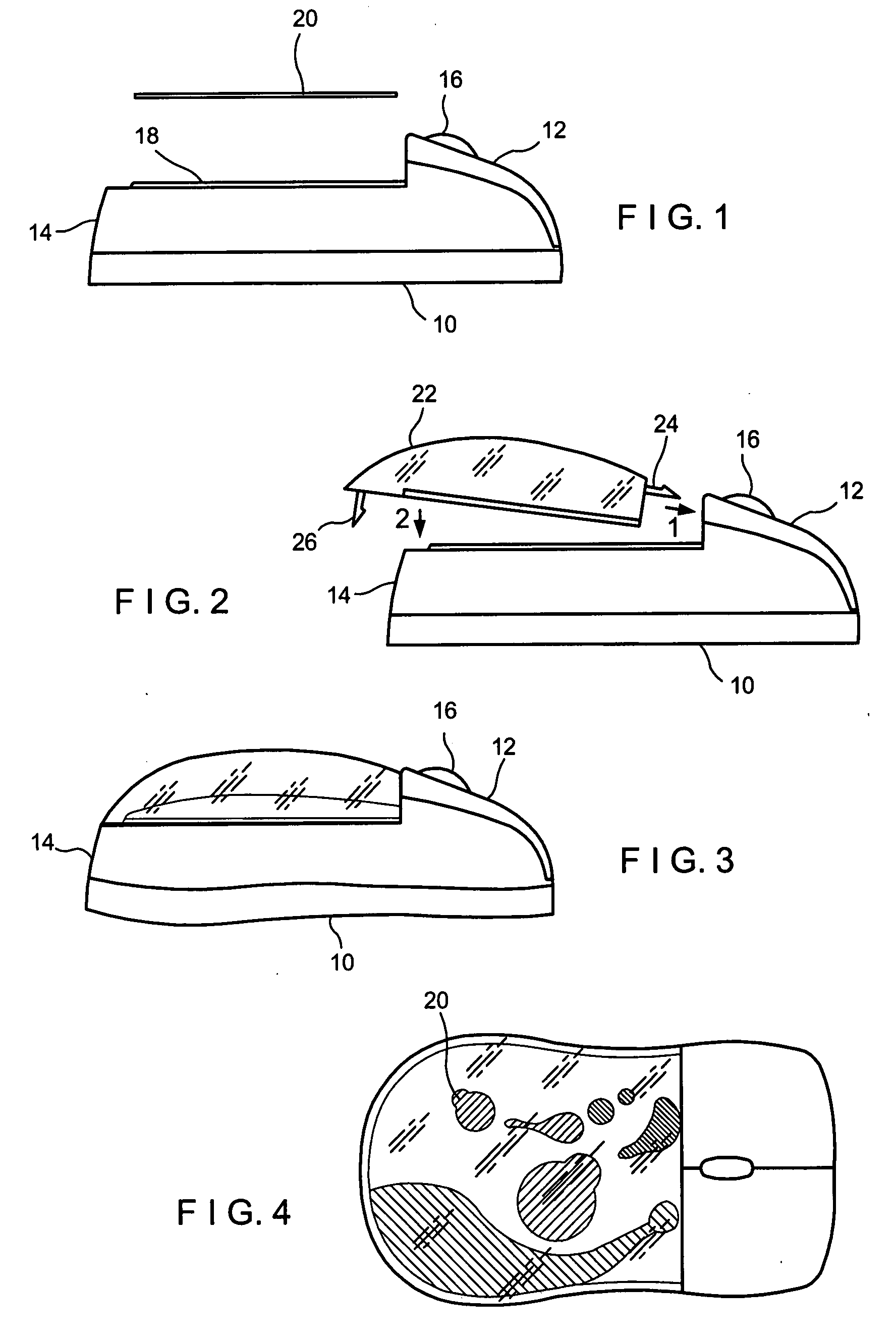
[0021]FIGS. 1-4 will be used to describe a first embodiment of the present invention. A computer mouse having a bottom surface 10, an upper surface 12, and a distending portion 14 is shown. Bottom surface 10 typically includes a roller ball or light (not shown) that is well known in the art. Bottom surface 10 is easily movable along a hard flat surface, such as a mouse pad. Upper surface 12 comprises a switch actuator portion 16, which is depicted in FIGS. 1-4 as a sliding roller. It is well known in the art that push buttons and other switch actuators can also be utilized for user interaction. Upper surface 12 also includes a graphical placement surface 18 upon which a graphical material 20 can be placed.

[0022]Referring specifically to FIG. 2, a detachable and transparent hand rest portion 22 is shown that includes a snap connector 24 and a snap connector 26. Hand rest portion 22 is first moved in the direction of directional arrow 1 to engage snap connector 24 to upper surface 12....


PUM


Abstract

A computer mouse is described comprising a bottom surface movable on a flat surface, an upper surface comprising a switch actuator portion, and a distending portion between the bottom surface and the upper surface. In the first embodiment of the present invention, a detachable and transparent hand rest portion is provided that can be affixed to the upper surface of the computer mouse. Graphical material can be placed beneath this detachable and transparent hand rest portion so that it is visible to the user. In a second embodiment of the present invention, a computer mouse comprises a bottom surface movable on a flat surface, an upper surface comprising a hand rest portion and a switch actuator portion, a distending portion between the bottom surface and the upper surface, and a detachable transparent cover overlaying said hand rest portion wherein said cover is sized to be selectively snapped on and off said computer mouse and incorporates sufficient space between the hand rest portion and said cover to permit placement of graphical material. In both preferred embodiments, the graphical material can be readily replaced at no additional costs.

Description

FIELD OF THE INVENTION[0001]This invention is generally directed to a computer mouse utilized to operate and control a computer. More specifically, the present invention provides an operational computer mouse having a bottom surface movable on a flat surface (such as a mouse pad), an upper surface comprising a switch actuator portion, a distending portion between the bottom surface and the upper surface, and a transparent hand rest portion on the upper surface under which graphical indicia can selectively be placed and is visible. The graphical indicia can take the form of a photograph, a corporate logo, computer instructions, a hologram, or any other two-dimensional information. The graphical indicia is easily replaceable by the user.BACKGROUND OF THE INVENTION[0002]A computer mouse is a well-known device used in conjunction with the operation of a personal computer. A computer mouse, in general, allows a user to change the position of a cursor on a screen or monitor to operate var...

Claims


Application Information

Patent Timeline
Patent Type & Authority Applications(United States)
IPC IPC(8): G06F3/033
CPCG06F3/03543
Inventor ROVERY, RITACROWLEY, KAREN
Owner ROVERY RITA
Why Eureka
Try Eureka