Digital Microform Imaging Apparatus

a microform imaging and digital technology, applied in the field of digital microform imaging apparatus, can solve the problems of inability to modify the user to accommodate a the optical system is enclosed and relatively fixed, and the reduction ratio range of device microfilm readers is still difficult to accommodate. the problem of a relatively large range of reduction ratios for film images, and achieves the effect of high resolution scans, low energy consumption, and short tim

Active Publication Date: 2008-11-20
E IMAGE DATA
View PDF14 Cites 11 Cited by
  • Summary
  • Abstract
  • Description
  • Claims
  • Application Information

AI Technical Summary

Benefits of technology

[0011]An advantage of an embodiment of the present invention is that it provides a compact microfilm viewer / scanner.
[0012]Another advantage of an embodiment of the present invention is that it can accommodate a broad range of image reduction ratios without the need to change zoom lenses.
[0013]Yet another advantage of an embodiment of the present invention is that it can accommodate a broad range of microform media types such as all film types and micro opaques.
[0014]Yet other advantages of an embodiment of the present invention are that it uses an area sensor to sense the image being displayed thereby eliminating the need for scanning individual images with a line sensor, and resulting in high resolution scans in a relatively short amount of time, for example one second.
[0015]Yet another advantage of an embodiment of the present invention is that it provides 360° image rotation.
[0016]Yet another advantage of an embodiment of the present invention is that it has low energy usage.

Problems solved by technology

A typical microfilm reader may have a range of zoom or magnification available to accommodate a portion of the reduction ratio range; however, this zoom range is limited and does not accommodate all reduction ratios.
Further, in a microfilm reader of the type in the '654 patent, the optical system is enclosed and relatively fixed, and cannot be modified by a user to accommodate a range of reduction ratios for which it is not designed.
These advantages have led to the development of microfilm readers which work in conjunction with a desktop computer; however, known peripheral device microfilm readers still have the problem of accommodating a relatively large range of reduction ratios for the film images.
There are several disadvantages to this approach which include the lenses end up missing or misplaced, the microfilm reader becomes undesirably large, and / or special instructions are required to swap out lenses which makes the different zoom lenses difficult to use.
Disadvantages include that the lens carriage is iteratively focused which can cause eye strain if a person is viewing the image during the focusing process, and this process takes time.
Another disadvantage is that the leads screws include backlash when reversing direction, which can make the iteratively focusing process difficult and / or imprecise, and the '398 patent is absent disclosure which discusses how to rectify such a problem.
Yet another disadvantage is that illumination system, film holder, lens and camera are all in line which creates a bulky system.
However, these patents, along with the other cited patents, together or separately, fail to disclose or suggest a compact digital microform imaging apparatus which can easily adapt to a broad range of reduction ratios, and also fail to disclose or suggest such a device while offering other modem features leveraging the potential versatility available in such a system used in conjunction with a computer system.

Method used


Image

  • Digital Microform Imaging Apparatus
  • Digital Microform Imaging Apparatus
  • Digital Microform Imaging Apparatus

Examples


Embodiment Construction

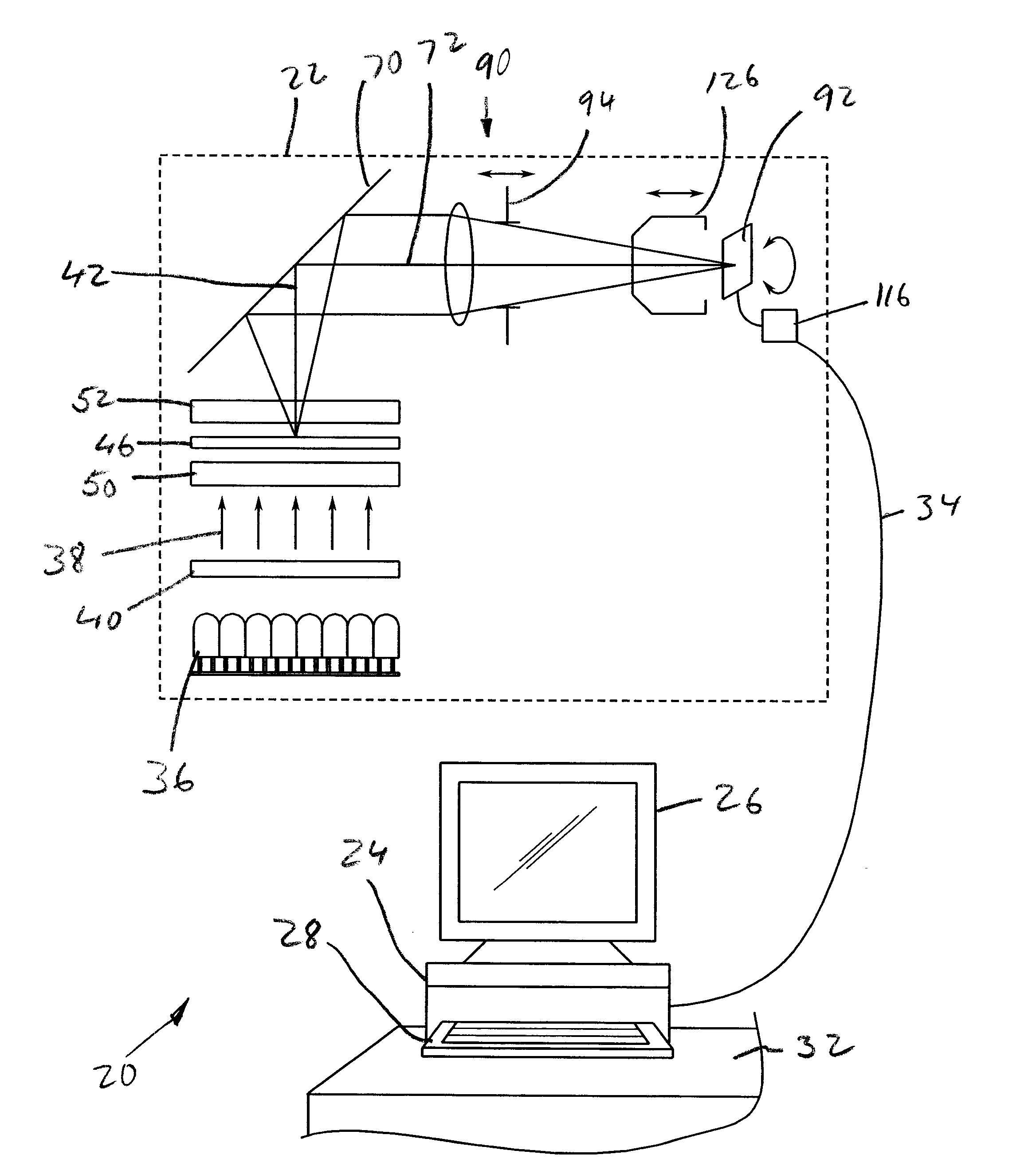
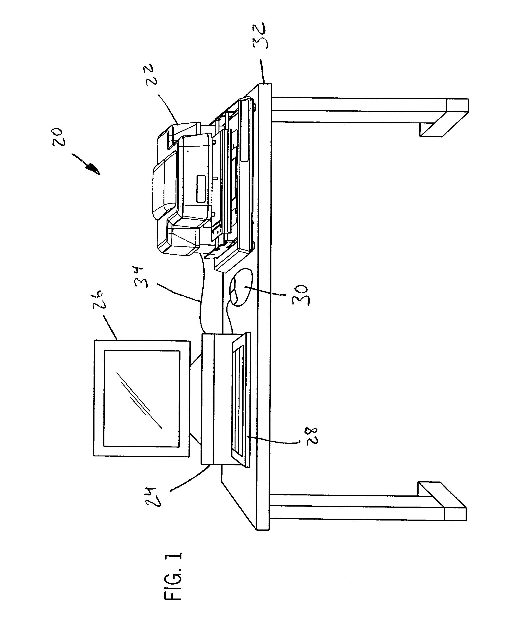
[0035]Referring now to the drawings, and more particularly to FIG. 1, there is shown a digital microform imaging system 20 which generally includes digital microform imaging apparatus (DMIA) 22 connected to a computer 24. Computer 24 can include one or more displays 26, and user input devices such as a keyboard 28 and mouse 30. DMIA 22 and computer 24 can be placed on a worksurface 32 of a desk, or other worksurfaces, for convenient access and ease of use. DMIA 22 can be electrically connected to computer 24 via cable 34, which may provide communication using a FireWire IEEE 1394 standard, for example.

[0036]Computer 24 can be connected to a printer (not shown) or connected / networked to other computers or peripheral devices (also not shown) to print, store or otherwise convey images produced by DMIA 22. Although cable 34 is described as an electrical type cable, alternatively DMIA 22 and computer 24 can communicate via fiber optics, or wirelessly through infrared or radio frequencies...


PUM


Abstract

A digital microform imaging apparatus which includes an approximately monochromatic illumination source transmitting an incident light through a diffuse window along a first optical axis of the apparatus. A microform media support is configured to support a microform media after the diffuse window and along the first optical axis. An approximately 45 degree fold mirror reflects the incident light transmitted through the microform media approximately 90 degrees along a second optical axis. An imaging subsystem includes a lens connected to a first carriage which is linearly adjustable approximately parallel with the second optical axis, and an area sensor connected to a second carriage which is linearly adjustable approximately parallel with the second optical axis.

Description

FIELD OF THE INVENTION[0001]The present invention relates to a digital microform imaging apparatus.BACKGROUND OF THE INVENTION[0002]Microform images are useful in archiving a variety of documents or records by photographically reducing and recording the document in a film format. Examples of typical microform image formats include microfilm / microfiche, aperture cards, jackets, 16 mm or 35 mm film roll film, cartridge film and other micro opaques. A microfiche article is a known form of graphic data presentation wherein a number of pages or images are photographically reproduced on a single “card” of microfiche film (such as a card of 3×5 inches to 4×6 inches, for example). Any suitable number of pages (up to a thousand or so) may be photographically formed in an orthogonal array on a single microfiche card of photographic film. The microfiche film may then be placed in an optical reader and moved over a rectilinear path until an image or a selected page is in an optical projection p...

Claims


Application Information

Patent Timeline
Patent Type & Authority Applications(United States)
IPC IPC(8): H04N1/00G03B21/10H04N1/04H04N1/387G03B21/11
CPCG03B21/11G03B27/34G03B27/53H04N1/02409H04N1/028G03B17/02H04N1/0288H04N1/195H04N1/19589H04N2201/041H04N1/00267H04N1/02805G02B7/09G02B7/182G02B17/08G03B21/115
Inventor KAHLE, TODD A.
Owner E IMAGE DATA
Why Eureka
Try Eureka