Two-chip type f Theta lens of microcomputer electric laser scanning device

A technology of laser scanning device and micro-electromechanical mirror, which is applied in the field of two-piece fθ lens

Inactive Publication Date: 2009-10-28
E PIN OPTICAL IND
View PDF13 Cites 0 Cited by
  • Summary
  • Abstract
  • Description
  • Claims
  • Application Information

AI Technical Summary

Problems solved by technology

[0016] Yet another object of the present invention is to provide a new type of micro-electro-mechanical laser scanning device with a two-piece fθ mirror. The technical problem to be solved is to make it possible to correct distortion due to the deviation of the scanning light from the optical axis, resulting in the main scanni

Method used


Image

  • Two-chip type f Theta lens of microcomputer electric laser scanning device
  • Two-chip type f Theta lens of microcomputer electric laser scanning device
  • Two-chip type f Theta lens of microcomputer electric laser scanning device

Examples


no. 1 example

[0107] The first lens and a second lens of the two-piece type fθ lens of the present embodiment are both crescent-shaped lenses with a concave surface on the side of the micro-electromechanical mirror. The four optical surfaces are aspherical surfaces, and formula (2) is used to design aspheric surface formulas; the second optical surface of the first lens and the third optical surface of the second lens are aspherical surfaces, and formula (2) is used to design aspheric surface formulas . Its optical characteristics and aspheric parameters are shown in Table 1 and Table 2 below.

[0108] Table 1. The fθ optical characteristics of the first embodiment

[0109]

[0110] Table two, the optical surface aspherical parameters of the first embodiment

[0111]

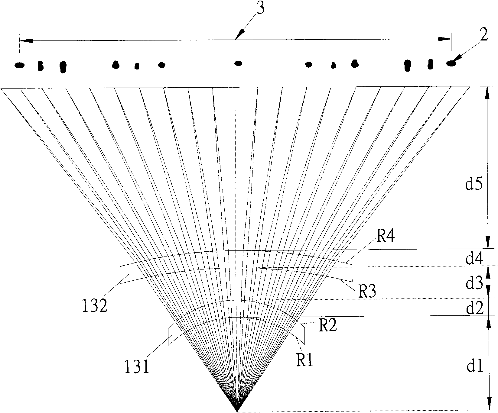
[0112] The optical path diagram of the optical surface of the two-piece fθ lens formed through this is as follows Figure 5 Shown is the optical path diagram of the first preferred embodiment of the present invention...

no. 2 example

[0116] The first lens and a second lens of the two-piece type fθ lens in this embodiment are both crescent-shaped lenses with a concave surface on the side of the micro-electromechanical mirror. The first optical surface of the first lens is an aspherical surface, and the use formula (3) design for the aspheric surface formula; be the aspherical surface at the second optical surface of the first eyeglass and the third learning surface of the second eyeglass, use formula (2) to be the aspheric surface formula design; the 4th learning surface of the second eyeglass is for the sphere. Its optical characteristics and aspheric parameters are shown in Table 4 and Table 5 below.

[0117] Table 4. The fθ optical characteristics of the second embodiment

[0118] fs=155.0

optical surface

Radius of curvature (mm)

dThickness (mm)

nd refractive index

(optical surface)

(curvature)

(thickness)

(refraction index)

MEMS reflective...

no. 3 example

[0125] The first lens and a second lens of the two-piece type fθ lens of the present embodiment are all crescent-shaped and the lens whose concave surface is on the side of the micro-electromechanical mirror is formed, and the first optical surface of the first lens and the fourth lens of the second lens are The optical surface is a spherical surface in the sub-scanning direction; the second optical surface of the first eyeglass and the third optical surface of the second eyeglass are aspherical surfaces, and the formula (2) is used to design the aspheric surface formula; the first optical surface of the first eyeglass and the third optical surface of the second eyeglass The fourth optical surface of the second lens is an aspheric surface in the main scanning direction, and the formula (3) is used to design the aspheric surface formula. Its optical characteristics and aspheric parameters are shown in Table 7 and Table 8 below.

[0126] Table seven, fθ optical characteristics o...


PUM


Abstract

The invention relates to a two-chip type f Theta lens of a microcomputer electric laser scanning device, which is provided with a first lens and a second lens, wherein the first lens and the second lens both consist of crescent-shaped lenses with concaves positioned at the side of a microcomputer electric reflector. The first lens is provided with a first optical surface and a second optical surface which both mainly convert scanning beam optical spots in a nonlinear scanning relationship between an angle reflected by the microcomputer electric reflector and time into scanning beam optical spots in a linear scanning relationship between distance and time. The second lens is provided with a third optical surface and a fourth optical surface which both mainly modify and focus the scanning beam of the first lens on a target object. The first lens and the second lens both satisfy a specific optical condition, so that the effect of linear scanning and the purpose of high-resolution scanning can be achieved by the arrangement of the first lens and the second lens.

Description

technical field [0001] The present invention relates to a two-piece fθ lens of a micro-electromechanical laser scanning device, in particular to a micro-electromechanical mirror used to correct a simple harmonic motion to produce a sinusoidal angle change over time to achieve laser The two-piece fθ lens of the MEMS laser scanning device for the linear scanning effect required by the scanning device. Background technique [0002] At present, the laser scanning unit LSU (Laser Scanning Unit) used in the laser beam printer LBP (Laser Beam Print) uses a high-speed rotating polygon mirror to control the scanning action of the laser beam (laser beam scanning). For example, the US patent US7079171, US6377293, US6295116, or as described in Chinese Taiwan patent I198966. The principle is briefly described as follows: use a semiconductor laser to emit a laser beam (laser beam), first pass through a collimator (collimator), and then pass through an aperture (aperture) to form a parall...

Claims


Application Information

Patent Timeline
IPC IPC(8): G02B26/10B41J2/47G03G15/00
Inventor 施柏源
Owner E PIN OPTICAL IND
Why Eureka
Try Eureka